Man iSea Operating Instructions Manual Download Page 119

Connecting cable

117

Read this manual carefully before starting any work!
This is particularly applicable to the chapter “General Safety Instructions” 
and the respective safety instructions in the chapters.

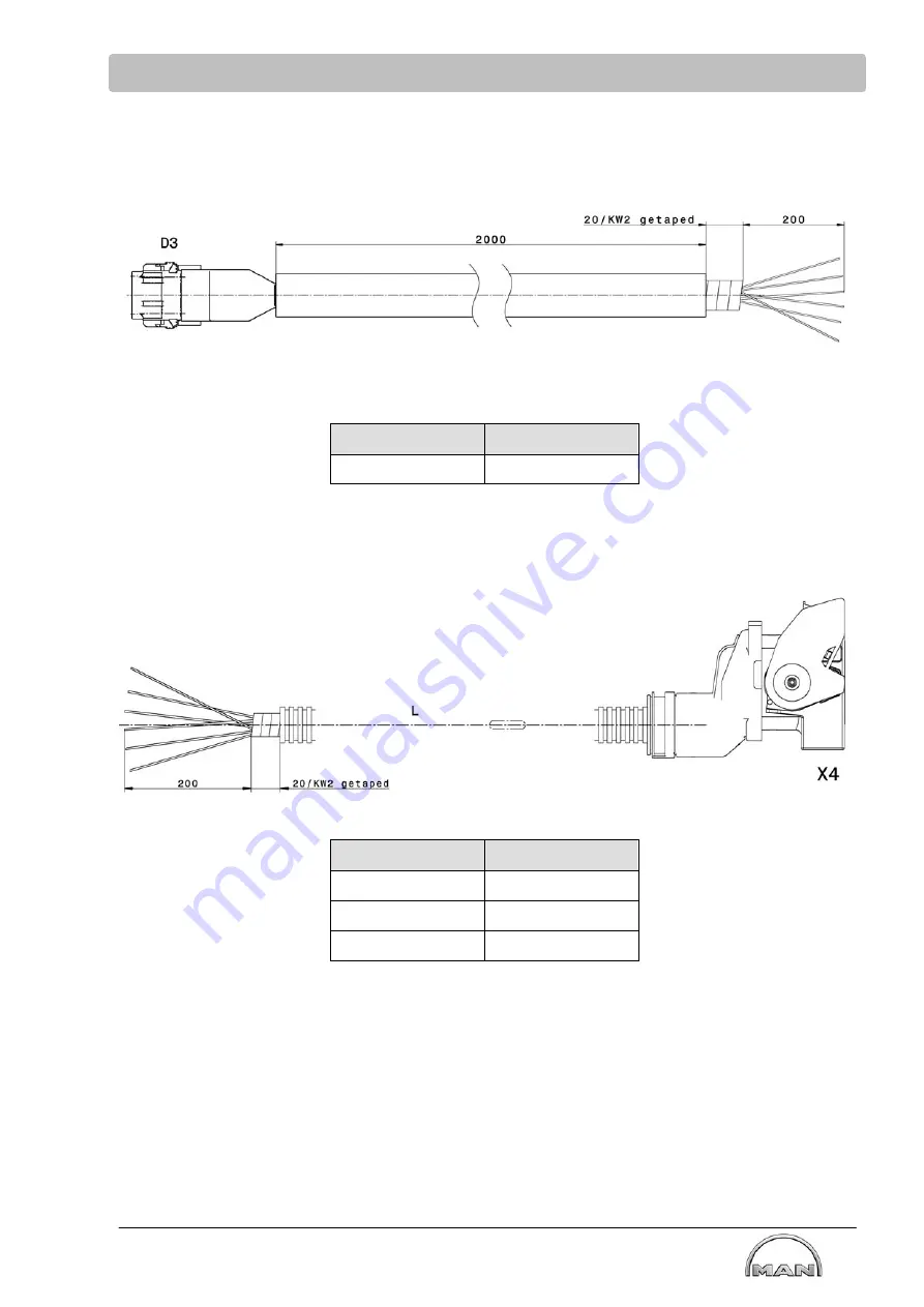
D3 bridge display C - Inputs CC

Length L

Part number

2 m

51.25411-6113

X4 E-box - ship

Length L

Part number

10 m

51.25411-6114

20 m

51.25411-6093

29 m

51.25411-6124

Summary of Contents for iSea

Page 1: ......

Page 2: ......

Page 3: ...Operating Instructions MAN Intelligent Marine Safeguard System iSea i Sea Class Translation of the original instructions 51 99587 5043 Version 01...

Page 4: ...change the contents of this document The same applies to changes to the context of individual chapters and or the whole document MAN Truck Bus SE assumes no liability for any damages arising from non...

Page 5: ...hazards 14 2 7 Safety equipment 17 2 7 1 Functional test emergency stop on the E box 17 2 8 Conduct in the even of hazards and accidents 18 2 9 Signage 19 2 10 Environmental protection 20 3 Functiona...

Page 6: ...face E box engine 60 8 6 Installation of the bridge display 61 9 Control and operation of the E box and the displays 63 9 1 Keyboard functions of the electronics box 63 9 1 1 Operating engine from eng...

Page 7: ...play 122 14 1 Parametrization 122 14 2 Possible error messages 125 15 Parametrization of emergency drive on 7 touch display 127 15 1 Parametrization 127 16 2 1 EEC1 138 16 Interface description classi...

Page 8: ...carefully before starting any work This is particularly applicable to the chapter General Safety Instructions and the respective safety instructions in the chapters 19 Shipyard wiring diagram 159 20 D...

Page 9: ...ons and are necessarily of a general nature since only the installer is familiar with details of the installation The recommendations provided in these instructions should be considered general exampl...

Page 10: ...tion Check for the most current information before you start any job MAN dealers will have the most current information 1 4 Liability for material defects Claims for liability for material defects can...

Page 11: ...eason S WARNING Describes a potentially hazardous situation that may lead to severe or fatal injuries if it is not avoided For this reason S CAUTION Describes a potentially hazardous situation that ma...

Page 12: ...y of the product is not affected by the procedures that are used 2 2 Proper use DANGER Risk of damages to the engine due to improper use Expiry of operating permit For this reason S Use the engine onl...

Page 13: ...f MAN any obligation of guarantee or warranty on the part of MAN for damage and defects that are attributable to the unauthorized modification becomes null and void Moreover MAN does not assume any li...

Page 14: ...ience as well as knowledge of the relevant regulations are capable of carrying out the duties assigned to them professionally S A qualified electrical technician is someone who based on his technical...

Page 15: ...leeves and without protruding parts They are used primarily to protect against injuries climatic influences and dirt or contamination Do not wear any rings necklaces or other jewelry on the body while...

Page 16: ...or carrying out any work on the electrical system deenergize the system and check that it is deenergized S Shut off the voltage supply and secure it from being switched on again before completing main...

Page 17: ...all clear Hot service products WARNING Risk of scalding by hot service products For this reason S Wear personal protective equipment S Follow the accident prevention regulations S Observe workplace s...

Page 18: ...d contacts For this reason S When installing the plug first open the plug lock completely and then insert the plug connector and lock it S Protect removed plug connectors and contacts against dirt S C...

Page 19: ...uption hazardous situations for human beings and property are ruled out The emergency stop facility must always be easily accessible DANGER Risk of life from non functional safety equipment and device...

Page 20: ...onduct safety training S Keep entry routes clear for emergency vehicles In case of an accident Act correctly S Remain calm S Shut down the engine immediately using the emergency stop button S Initiate...

Page 21: ...Operating Instructions Electrical voltage Only electricians may carry out work in working areas marked in this manner Unauthorized persons should not enter areas marked in this manner Hot surfaces Ho...

Page 22: ...ndling of service products Considerable damage is caused to the environment For this reason S Comply with the country specific safety regulations S Use appropriate and suitably sized containers to col...

Page 23: ...gine stop is permissible if no other controllable system reaction can be guaranteed due to the system Safety targets As a result the following safety targets and associated safety conditions were defi...

Page 24: ...ined function specifically both in case of suspected defective and in case of confirmed defective Engine stop is permissible if no other controllable system reaction can be guaranteed due to the syste...

Page 25: ...is installed which is controlled by the MCS control unit or the drive lever control unit via the E Box The combustion engine is coupled directly to the ship s propeller via a closed drive train A tor...

Page 26: ...this is provided by the MCS control unit via CAN In order to change the direction of rotation of the ship s propeller a reverse gearbox is installed which is controlled by the MCS control unit or the...

Page 27: ...ructions in the chapters 3 3 Boundary conditions and consequences of non observance The function reverse gearbox with permanent activation must be installed The gearbox valves must be controlled direc...

Page 28: ...dth To permit malfunction free operation of the electronic control of the engine and the aftertreatment system it is mandatory that the MAN overall system is protected from external effects via the vo...

Page 29: ...ded at both ends If the cables are longer than 10 m a further shielding contact point to functional ground must be provided at least every 10 m The aftertreatment systems require shielding of the cabl...

Page 30: ...magnetic compatibility 28 Read this manual carefully before starting any work This is particularly applicable to the chapter General Safety Instructions and the respective safety instructions in the c...

Page 31: ...this manual carefully before starting any work This is particularly applicable to the chapter General Safety Instructions and the respective safety instructions in the chapters 5 System overview Syst...

Page 32: ...ead this manual carefully before starting any work This is particularly applicable to the chapter General Safety Instructions and the respective safety instructions in the chapters System overview non...

Page 33: ...can reduce the power output and speed of the engine to prevent consequential damage For the non classified version an engine stop can optionally be specified for certain engine parameters in case of a...

Page 34: ...fety instructions in the chapters E box without acceptance non classified system Weight and dimensions identical with without display Weight 13 kg Dimension A 417 5 mm Dimension B 330 mm Dimension C w...

Page 35: ...starting any work This is particularly applicable to the chapter General Safety Instructions and the respective safety instructions in the chapters Opening closing the E box 1 Turn locking system cloc...

Page 36: ...r control unit The drive lever control unit sets the speed request specified by the operator for the system or the engine control unit The engine control unit uses the speed request and various margin...

Page 37: ...the E box It is the carrier board for the control plate s or the MCS and MCS SU control unit E box with acceptance 1 Motherboard for MCS 2 Motherboard for MCS SU Motherboard for MCS SU 2 is only insta...

Page 38: ...h Test not active Switch OFF S4 S5 Switching Emergency stop active at X7 or at X4 DIP switch X4 active Switch OFF S6 Self locking of emergency stop active or not active DIP switch Static switch active...

Page 39: ...ivery state bottom JP4 3 must be switched to top Default Switch Function To be found State Pin Switch position S1 S2 S3 Test only Overspeed test active or not active DIP switch Test not active Switch...

Page 40: ...m as well as displays and engine controllers EDC These regulate control and monitor the engine operating parameters and the drive train They support the marine specific components that are required fo...

Page 41: ...tions in the chapters 6 2 4 Connector board Installation location The connector board is attached at the front in the terminal box 1 Connector board Function The connector board establishes signal con...

Page 42: ...ive lever control unit is supplied with the engine as a classified unit on behalf of the customer by MAN The integrated drive lever control unit will only be installed in the E box and commissioned on...

Page 43: ...Components of the internal drive lever control unit Termination at the end of the bus on the drive lever Selection of the utilized drive lever 2 3 and control strip 4 examples will also be implemented...

Page 44: ...iring of the internal drive lever control unit Example E box with acceptance and 2 operator s stands Bridge Engine control room 1 Terminating resistor 2 Drive lever bridge 3 Drive lever engine control...

Page 45: ...he respective safety instructions in the chapters Example E box without acceptance with 2 engines and 2 drive levers 1 Drive lever 1 2 Drive lever 2 3 CAN bus terminating resistor 4 E box port 5 Cable...

Page 46: ...he influence of electromagnetic radiation e g cell phones on the drive lever control unit Adapters are required for connection of the CAN bus cable to the drive lever When installing the wiring ensure...

Page 47: ...erable connecting cables are shown for Drive lever Drive lever E box Drive lever Cross communication E box E box only possible for E box non classified L 40 PIN Bush Length L Part number 2 m 51 25449...

Page 48: ...nged Standard setting S1 to the right S1 Drive lever terminating resistor switch S2 Cross communication terminating resistor switch NOTICE Malfunctions due to redundancy The CAN termination of the cro...

Page 49: ...pters 7 1 3 Drive lever control special function on the plug X88 In the case of internal drive lever control the partial access to the X88 plug is the same for classified and non classified engines Fo...

Page 50: ...al 4 20mA OUT B2 blue Gearbox Ubat OUT oder X4 D1 C2 red black Trolling ON OFF OUT B3 red Gearbox Ubat OUT oder X4 D1 C3 black white Slip Grip ON OFF OUT B4 green Proportional Ventil A OUT C4 blue bla...

Page 51: ...ed with the engine and as a classified unit on behalf of the customer by MAN The external drive lever control unit will be installed in the engine room and commissioned on site A drive lever control u...

Page 52: ...ntial free and can be used at the E box at plug X9 for engine synchronization Connecting cable Length L Part number 3 m 51 25411 6100 5 m 51 25411 6101 X9 connector set consists of Piece MAN part numb...

Page 53: ...perator s stand that is assigned to the drive lever control unit has occurred The signal is used in the classified system for local remote switching in the non classified system for start blocking Hen...

Page 54: ...r control via battery terminal 30 31 The safeguards provided by the manufacturer are to be observed when connecting the drive lever systems to the battery voltage If the power consumption of the drive...

Page 55: ...safety instructions in the chapters 7 2 3 Speed signal for engine synchronization A supplied speed signal is provided at plug X9 pin B7 and C7 This can be input into the drive lever control unit for e...

Page 56: ...ctionality of start blocking is only used in the non classified engines Start blocking guarantees that the engine cannot be started when the gearbox is engaged NOTICE Do not start the engine with the...

Page 57: ...this manual carefully before starting any work This is particularly applicable to the chapter General Safety Instructions and the respective safety instructions in the chapters 7 3 Dimensions of driv...

Page 58: ...that operating personnel be informed that they are responsible for the safety of the individuals who enter the engine room Personnel Installation and commissioning may only be performed by MAN employ...

Page 59: ...y and securely S Keep access to the safety equipment devices clear NOTICE False alarms due to missing or inadequate grounding of the E box For this reason S Connect ground connection of the E box with...

Page 60: ...AN Service X16 Connection of override button for alarm system X17 Display on the bridge as to whether Local or Remote status is active X23 Without function only reserve X24 Without function only reser...

Page 61: ...n X6 CAN connection of the display instruments displays X7 Reserve X8 Gearbox feedback signals X9 Connection for external drive lever control X10 Connection for diagnostics software only for MAN Servi...

Page 62: ...cable to the chapter General Safety Instructions and the respective safety instructions in the chapters 8 5 Interface E box engine Connect cable harness to plug connection 1 engine X1 at E box Additio...

Page 63: ...ssible distance Installation location Open Bridge and or Engine control room The touch display can be delivered in 5 or 7 inch The 5 inch touch display is only available for the non classified version...

Page 64: ...ch display Connection gray for Voltage supply CAN 1 USB Digital output only with 7 inch display Connection black for Interface CAN 2 see page 138 Video only with 7 inch display Only present with 7 inc...

Page 65: ...unctions 9 1 Keyboard functions of the electronics box Electronic box classified 1 Engine room display AL see page 69 Local operator s stand with engine control function 2 Quit button alarm for AL 3 R...

Page 66: ...work This is particularly applicable to the chapter General Safety Instructions and the respective safety instructions in the chapters Electronic box non classified 1 Engine room display AL see page...

Page 67: ...of command from Local to an operator s stand Press the Remote button 1 to make the command request from the engine room to the operator s stand of the ship The command request must be confirmed via t...

Page 68: ...g the button 2 twice The check light 3 indicates that the engine control room ECR has been activated The check light 4 indicates that the bridge has been activated After command is taken over the engi...

Page 69: ...switch off of the battery main switch Parts of the aftertreatment system are damaged For this reason S After 2 hours main battery switch off Command transfer by pressing the Local button 2 on the E bo...

Page 70: ...tertreatment system resulting from use of the emergency stop button Unlock To unlock the emergency stop button the cap must be turned clockwise to unblock it Alarm must be acknowledged and reset Then...

Page 71: ...ed with a finger or with gloves A swiping function is not available The display is a display system which shows engine operating values that it receives from the alarm system or the safety system via...

Page 72: ...l control is effected via pressing the Local ON OFF button on the alarm display twice Request on first activation flashing LED behind the 8 buttons flashing green bar on the screen acoustic message ac...

Page 73: ...show the maximum potential applications of the display functions Main menu Display alarm system Display safety system only with classified version 1 Main page 2 Alarm page 3 Settings 4 Service page 5...

Page 74: ...aximum S Engine speed S Fuel consumption S Drive lever position S Relative load S Engine oil pressure S Engine oil temperature S Engine oil pressure upstream of filter S Differential pressure engine o...

Page 75: ...Fuel consumption page The following values can be queried S Engine speed S Fuel consumption S Trip fuel consumption S Overall fuel consumption S DEF AdBlue AUS32 AUS40 consumption S DEF AdBlue AUS32 A...

Page 76: ...chapters Settings The following settings can be made on this page S Languages available in German English Italian Spanish French Russian Chinese S Units metric US standard S Background Day mode brigh...

Page 77: ...ge password are required Prerequisites for adjusting the values 1 Idle speed Idle speed is set to 600 rpm ex works S Engine at idle S Driving lever must stand at 0 2 Intermediate speed control The PI...

Page 78: ...at can be terminated by pressing a button It is possible to select from several languages for optimum adaptation to the requirements of users The data can be shown in either metric or US standard unit...

Page 79: ...ions shown here show the maximum potential applications of the display functions Configuration commissioning page Non classified application Switching the display between Single engine display or Dual...

Page 80: ...ed in accordance with the alarm state yellow red The following queries are possible in the main menu structure 1 Main pages 1 3 2 Alarm page 3 Settings Languages time etc 4 Service page 5 Electronic c...

Page 81: ...or CAN connection not available Video function optional remains The following values can be queried S Engine speed RPM S Oil pressure S Oil temperature S Coolant temperature S Drive lever position S R...

Page 82: ...ion S SPN and time stamp S Values actual value S Limit values extreme value A permanent tone is sounded upon occurrence of an alarm on the engine page on Emission page only in the case of engines with...

Page 83: ...ledged on the display Display engine control room S An alarm or warning message can be acoustically and visually acknowledged and reset at the display in the engine control room Complete acknowledgmen...

Page 84: ...de bright dark S Date dd mm yyy or mm dd yyyy d day m month y year S Time 12 hr or 24 hr S Stealth mode On Off In stealth mode the background lighting of the display is switched off after a programmed...

Page 85: ...he value the measurement value itself and the status display of the value warning alarm and signal error are represented as an LED When the LED ist switched off no value or sensor is stored The values...

Page 86: ...lable in English Here the detailed output of the control unit error memory is displayed and is intended for the MAN authorized service engineer The error page DM1 has up to three tabs S ECU EDC S ECU...

Page 87: ...the digital input is possible by operating the field Keyboard appears Keyboard commands OK ENTF ESC C Selectable between 24 V NC normally open and 0 V NO normally closed If the conditions are not met...

Page 88: ...d RPM S Fuel consumption S Drive lever position S Relative load S Trip fuel consumption S DEF AdBlue AUS32 AUS40 consumption S DEF AdBlue AUS32 AUS40 overall consumption S Engine operating hours Query...

Page 89: ...arbox shift to reverse button Reverse S Engine speed increase button RPM S Engine speed decrease button RPM Deactivation by pressing the EM Drive Cancel button twice independent of the emergency drive...

Page 90: ...e newly selected operator s stand has activated the drive function in the previous display is automatically deactivated The page will be closed General information S In case of a malfunction of the em...

Page 91: ...menu The start button is unlock by swiping the lock button to the right Repeated swipe locks the button S Start engine with button HOLD TO START ENGINE see engine rpm S Stop engine with button STOP EN...

Page 92: ...can be retrieved in the sub menu Aftertreatment system The following values can be queried Page 1 bank A S Exhaust gas temperature downstream of exhaust gas turbocharger A S Exhaust gas back pressure...

Page 93: ...ce In the event that an engine and aftertreatment error occur simultaneously the error page of the engine is displayed as having higher priority The operator can switch to the error page of the aftert...

Page 94: ...limit values see following table To prevent engine operation without DEF AdBlue AUS32 AUS40 and the consequential increase in NOx emissions the DEF AdBlue AUS32 AUS40 tank must be refilled DEF tank le...

Page 95: ...ive quality sensor cannot detect insufficient reduction agent quality the system continues to detect an error via the NOx sensor Errors and manipulation aftertreatment system Detection of an error or...

Page 96: ...tment system are separated into warning messages and alarm messages Emissions related warning intermittent tone Operator is informed visually and acoustically about imminent incorrect operation of the...

Page 97: ...emissions history memory is only shown for one engine The print out contains the following information S Date of printing including the operating hours of the engine at the time of print out S Engine...

Page 98: ...structions in the chapters Printing options format The operator is offered various formats for printing S pdf S xps S txt S csv Recommendation CSV Export here all logged messages are displayed chronol...

Page 99: ...igure next to the symbol Warning symbol yellow for I O alarm A yellow warning symbol illuminates when an active error is present Symbol flashes Errors alarms not acknowledged Symbol static Errors alar...

Page 100: ...connecting cable for the display systems and instruments is connected to the E box at plug X6 The CAN cable must always be ended with a terminating resistor The CAN terminating resistor must fundament...

Page 101: ...particularly applicable to the chapter General Safety Instructions and the respective safety instructions in the chapters Adapter cable Length L Part number 0 5 m 51 25411 6133 Parts to the connectin...

Page 102: ...stop Alarms horn Start blocking The 32 pin mating plug shipyard plug is supplied by MAN A wiring diagram for the connection of a ignition lock for operation of the ignition can be found on page 101 Co...

Page 103: ...particularly applicable to the chapter General Safety Instructions and the respective safety instructions in the chapters Connection for the shipyard side wiring at shipyard plug X4 1 The active oper...

Page 104: ...stopping the engine can also be actuated by 1 an ignition switch 2 a button without ignition switch In this case the ignition is switched on and off via the impulse The engine is also started using a...

Page 105: ...re open circuit monitoring a terminating resistor of 18 k must also be connected in parallel to the last emergency stop button X4 Notstopp 1 Notstopp 2 B7 B6 18 k resistor for open circuit monitoring...

Page 106: ...it is thus possible to restore full engine power and thereby ensure the safety of the ship NOTICE Risk of damage to the engine due to ignoring alarms For this reason S The override system may only be...

Page 107: ...of the override button For the E box with acceptance The override button is connected to the plug X16 alarm system and X47 safety system For the E box without acceptance The override button is connec...

Page 108: ...le to the chapter General Safety Instructions and the respective safety instructions in the chapters Connecting cable Override button electronics box L 40 40 Length L Part number 3 m 51 25449 0041 10...

Page 109: ...General Safety Instructions and the respective safety instructions in the chapters Dimensions override button If the override button is installed afterwards a data set adjustment is necessary 57 49 4...

Page 110: ...canceled again at a coolant temperature of 90 C Error message can now be acknowledged and reset on the bridge display Override can now be deactivated and reset on the bridge display Safety system If t...

Page 111: ...verride system 109 Read this manual carefully before starting any work This is particularly applicable to the chapter General Safety Instructions and the respective safety instructions in the chapters...

Page 112: ...ion Panel EOP is optionally offered by MAN for non classified systems 12 1 1 General The Engine Operation Panel EOP 1 has the following functions Ignition on off Engine start stop Emergency stop Monit...

Page 113: ...nt buttons must be easily accessible For the dimensions of the Engine Operation Panel EOP see page Technical data General data Dimensions W x H x D 70 x 130 x 65 mm Console section Bx H 60 x 113 mm We...

Page 114: ...dered subsequently and integrated using plug connectors in the existing system Technical data General data Dimensions W x H x D 70 x 130 x 65 mm Console section Bx H 60 x 113 mm Weight Approx 0 5 kg E...

Page 115: ...tions and the respective safety instructions in the chapters 12 3 Connecting cables for the Engine Operation Panels EOP and EOP D Engine Operation Panel EOP E box and EOP EOP D L 40 14 5 Length L Part...

Page 116: ...manual carefully before starting any work This is particularly applicable to the chapter General Safety Instructions and the respective safety instructions in the chapters 12 4 Engine Operation Panel...

Page 117: ...e operation panels 115 Read this manual carefully before starting any work This is particularly applicable to the chapter General Safety Instructions and the respective safety instructions in the chap...

Page 118: ...structions and the respective safety instructions in the chapters 13 Connecting lines Connecting lines for classified engines are only tested up to 29 m and approved by MAN D1 bridge display A Power C...

Page 119: ...articularly applicable to the chapter General Safety Instructions and the respective safety instructions in the chapters D3 bridge display C Inputs CC Length L Part number 2 m 51 25411 6113 X4 E box s...

Page 120: ...e chapters X5 E box E box Only for non classified engines Length L Part number 2 m 51 25411 6094 5 m 51 25411 6095 10 m 51 25411 6096 20 m 51 25411 6097 25 m 51 25411 6126 29 m 51 25411 6127 X7 start...

Page 121: ...ticularly applicable to the chapter General Safety Instructions and the respective safety instructions in the chapters X8 E box gearbox feedback Length L Part number 8 m 51 25411 6098 X9 E box externa...

Page 122: ...r General Safety Instructions and the respective safety instructions in the chapters X17 E box Local Remote display Only for classified engines Length L Part number 8 m 51 25411 6102 X21 E box status...

Page 123: ...able to the chapter General Safety Instructions and the respective safety instructions in the chapters X41 E box status messages safety system to external ship system Only for classified engines Lengt...

Page 124: ...ment up to six displays with start stop function can be parametrized for each engine Here the 5 and 7 inch displays are equivalent That is the number of desired displays with start stop function can b...

Page 125: ...ty instructions in the chapters System configuration setting of the start stop stands available in the system Press button The following view is displayed In addition the maximum possible number of st...

Page 126: ...ss button The following view is displayed Free IDs that are not yet used in the system configuration are displayed under SELECT stand ID An ID can be selected via SELECT In principle it is irrelevant...

Page 127: ...nection Error message Unconfigured Start Stop stands A start stop stand with the ID 1 is found in the system configuration shown on the right although this was not parametrized Possible causes procedu...

Page 128: ...is parametrized with an ID that is already present in the system network Possible causes procedure S Re parametrize start stop stand in the display Unregister stand then configure again Example of an...

Page 129: ...two engines on one display is also excepted from this As maximum equipment up to six displays with emergency operation functionality can be parametrized for each engine 15 1 Parametrization Entry via...

Page 130: ...tructions in the chapters System configuration setting of the emergency operator s stands available in the system Press button The following view is displayed In addition the maximum possible number o...

Page 131: ...Press button The following view is displayed Free IDs that are not yet used in the system configuration are displayed under Choose stand ID An ID can be selected via SELECT In principle it is irrelev...

Page 132: ...than are available Re parametrize the system Error message Unconfigured Emergency Drive stands An operator s stand with the ID 1 is found in the system configuration shown on the right although this w...

Page 133: ...rametrized with an ID that is already present in the system network Possible causes procedure S Re parametrize operator s stand in the display Unregister stand then configure again Example of an error...

Page 134: ...aller Arbeiten sorgf ltig durchlesen Dies gilt insbesondere f r das Kapitel Allgemeine Sicherheitshinweise und die jeweiligen Sicherheitshinweise in den Kapiteln 16 Interface description classified en...

Page 135: ...Anleitung vor Beginn aller Arbeiten sorgf ltig durchlesen Dies gilt insbesondere f r das Kapitel Allgemeine Sicherheitshinweise und die jeweiligen Sicherheitshinweise in den Kapiteln Interface X9 clas...

Page 136: ...Anleitung vor Beginn aller Arbeiten sorgf ltig durchlesen Dies gilt insbesondere f r das Kapitel Allgemeine Sicherheitshinweise und die jeweiligen Sicherheitshinweise in den Kapiteln Interface X21 cla...

Page 137: ...ce description 135 Diese Anleitung vor Beginn aller Arbeiten sorgf ltig durchlesen Dies gilt insbesondere f r das Kapitel Allgemeine Sicherheitshinweise und die jeweiligen Sicherheitshinweise in den K...

Page 138: ...r Beginn aller Arbeiten sorgf ltig durchlesen Dies gilt insbesondere f r das Kapitel Allgemeine Sicherheitshinweise und die jeweiligen Sicherheitshinweise in den Kapiteln 17 Interface description non...

Page 139: ...ription 137 Diese Anleitung vor Beginn aller Arbeiten sorgf ltig durchlesen Dies gilt insbesondere f r das Kapitel Allgemeine Sicherheitshinweise und die jeweiligen Sicherheitshinweise in den Kapiteln...

Page 140: ...FF one byte value 2 If the sending control unit detects an error on a transmitted parameter or sensor value the following identifier is sent 0xFE00 two byte value 0xFE one byte value 18 2 Ship CAN int...

Page 141: ...drive leverage to EDC17 for classes engines 0x27 MCS idle or drive leverage 0xD0 Driving from Emergency stand 1 0xD1 Driving from Emergency stand 2 0xD2 Driving from Emergency stand 3 0xD3 Driving fr...

Page 142: ...0 4 per bit 0 offset Range 0 100 SAEJ1939 71 SPN 91 Byte 3 Load at current speed 1 per bit 0 offset Range 0 125 SAEJ1939 71 SPN 92 Byte 4 8 Default Value 0xFF FF FF FF FF Not supported 18 2 3 Turbocha...

Page 143: ...939 71 SPN 1184 Byte 3 4 Exhaust temperature after turbo 2 0 03125 C per bit 273 C offset Range 273 C 1735 C SAEJ1939 71 SPN 1185 Byte 5 8 Default Value 0xFF FF FF FF Not supported 18 2 5 Engine Tempe...

Page 144: ...set Range 0 bar 10 bar SAEJ1939 71 SPN 94 Byte 2 Extended Crankcase Blow by Pressure 0x FF Not supported Byte 3 Engine oil level 0 4 per bit 0 offset Range 0 100 SAEJ1939 71 SPN 94 Byte 4 Engine oil p...

Page 145: ...Exhaust Conditions Transmission repetition rate 500 ms Data length 8 bytes Identifier 0x18 FE F6 27 Byte 1 Exhaust back pressure 5 mbar per bit 0 mbar offset Range 0 1 25 bar SAEJ1939 71 SPN 81 Byte 2...

Page 146: ...yte 3 4 Alternator potential voltage 50 mV per bit 0 V offset Range 0 V 3212 75 V SAEJ1939 71 SPN 167 Byte 5 6 Electrical potential voltage 50 mV per bit 0 V offset Range 0 V 3212 75 V SAEJ1939 71 SPN...

Page 147: ...alue 0xFF Not supported Byte 2 Transmission Oil Level 0 4 per bit 0 offset Range 0 100 SAEJ1939 71 SPN 124 only two states supported 0 Low level detected 100 No low level detected Byte 2 Transmission...

Page 148: ...ernal UTC 1 min per bit 0 min offset Range 0 59 min SAEJ1939 71 SPN 960 Byte 3 Hours MAN internal UTC 1 h per bit 0 h offset Range 0 23 h SAEJ1939 71 SPN 961 Byte 4 Month MAN internal UTC 1 month bit...

Page 149: ...71 SPN 247 Byte 5 8 Total engine revolutions 0x FF FF FF FF Not supported 18 2 13 Fuel Economy Transmission repetition rate 100 ms Data length 8 bytes Identifier 0x18 FE F2 27 Byte 1 2 Fuel rate 0 05...

Page 150: ...Data length 8 bytes Identifier 0x18 FF 1C 27 Byte 1 Control Bits Bit 1 2 Status gearbox neutral position Value 00bin Gearbox not in neutral 01bin Gearbox in neutral 1xbin invalid interpretation as wi...

Page 151: ...nge 273 C 1735 C MAN specific similar to SAEJ1939 71 SPN 4363 Byte 7 8 SCR System 2 Catalyst Outlet Gas Temperature 0 03125 C per bit 273 C offset Range 273 C 1735 C MAN specific similar to SAEJ1939 7...

Page 152: ...ir Pressure 105 Sensor failure 2 Warning Alarm 0 Charge air Temperature 109 Sensor failure 2 Warning Alarm 1 Coolant Pressure 110 Sensor failure 2 Warning Alarm 0 Coolant Temperature 111 Sensor failur...

Page 153: ...Override 520192 Sensor failure 2 Warning Alarm 0 Engine Fuel Return Flow Pressure 520194 Sensor failure 2 Warning Alarm 0 Sea Water Temperature 520196 Sensor failure 2 Warning Alarm 1 Temperature Plu...

Page 154: ...Warning Lamp Status equals Warning 00bin no Warning active 01bin Warning active MAN specific Bit 5 6 Red Stop Lamp Status equals ALARM 00bin no Alarm active 01bin Alarm active MAN specific Bit 7 8 no...

Page 155: ...byte 3 to 6 Byte 7 8 not used 0xFFFF Hint The SPN is set to Zero if there is no fault active If there is more than one failure active the DM1 Message is transmitted as multi packet message Header mess...

Page 156: ...M 00bin no Alarm active 01bin Alarm active MAN specific Bit 7 8 not used 11bin Byte 3 not used 0xFF Byte 4 Bits 1 8 SPN 8 least significant bits of SPN bit 8 most significant 1st active fault Byte 5 B...

Page 157: ...6 8 SPN most significant bits of SPN bit 7 is MSB of SPN Byte 4 Bits 1 7 Occurrence Counter set to 0000001bin Bit 8 CM SPN conversion method set to 0bin Byte 5 Bits 1 8 SPN 8 least significant bits of...

Page 158: ...1CEBFF27x P_MAN Engine_to_global Rx 8 01 D1 FF FE 00 C2 01 00 4 300000 1CEBFF27x P_MAN Engine_to_global Rx 8 02 0C 81 01 FF FF FF FF 5 200000 1CECFF27x BAM_MAN Engine_to_global Rx 8 20 0A 00 02 FF CA...

Page 159: ...s would be described The number of Use Bytes in the BAM message would increase to 14 If more than one further error was added the number of P messages would increase Thus maximum of 10 errors transmit...

Page 160: ...ual carefully before starting any work This is particularly applicable to the chapter General Safety Instructions and the respective safety instructions in the chapters 18 2 18 DISPLAY Receive Message...

Page 161: ...ad this manual carefully before starting any work This is particularly applicable to the chapter General Safety Instructions and the respective safety instructions in the chapters 19 Shipyard wiring d...

Page 162: ...ram and schematic diagram 160 Read this manual carefully before starting any work This is particularly applicable to the chapter General Safety Instructions and the respective safety instructions in t...

Page 163: ...Wiring diagram Marine shipyard classified...

Page 164: ......

Page 165: ...Wiring diagram Marine shipyard non classified...

Page 166: ......

Page 167: ...ories 165 Read this manual carefully before starting any work This is particularly applicable to the chapter General Safety Instructions and the respective safety instructions in the chapters 20 Direc...

Page 168: ...Directories 166 Read this manual carefully before starting any work This is particularly applicable to the chapter General Safety Instructions and the respective safety instructions in the chapters...

Page 169: ...he vehicle Controller Area Network E box Electronic box terminal box EDC Electronically controlled diesel injection Electronic Diesel Control etc and so on etcetera e g For example h Hour kg Kilogram...

Page 170: ......

Page 171: ......

Page 172: ......

Reviews: