background image

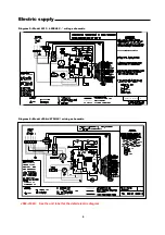
Electric


supply 


Diagram


5:


Model L013

L030HLC -*


wiring


schematic 


Diagram


6:


Model J036~J072HLC-*


wiring


schematic 


J086-J142H:    See the unit label for the detail electric diagram


SCHEMATIC DIAGRAM

  B

    A

Summary of Contents for J036HHC

Page 1: ...ing of installation and service personnel Unqualified individuals should not attempt to interpret these instructions or install this equipment Read instructions carefully before unpacking installing and operating unit Inspection Inspection Inspection Inspection This heat pump has been factory inspected however we recommend you check the carton and inspect the unit for concealed shipping damage Not...

Page 2: ...acent to the conditioned space provide an insulated return air duct with at least one 90 degree bend If a free return air system is used position the filter side of the unit as close as possible to the return air grille Note The unit is shipped from the factory with access to the electrical box such that return air enters the unit from the right side when facing the electric control box Model Mode...

Page 3: ...D ROD BY OTHERS ADJUSTABLE SLOT IN HANGER BRACKET WASHER HANGER BRACKET VIBRATION ISOLATION GROMMET WASHER BY OTHERS MUST COVER ENTIRE BOTTOM OF GROMMET RETAINING NUTS BY OTHERS NOTES NOTES NOTES NOTES 1 AN INTERNAL BLOWER ACCESS PANEL IS PROVIDED FOR SERVICING UNIT FULL SERVICE PANELS ARE AVAILABLE ON ALL SIDES 2 THE ELECTRICAL CONTROL PANEL IS LOCATED INSIDE THE UNIT 3 DO NOT SCREW DUCTWORK INTO...

Page 4: ...T VIBRATION ISOLATION GROMMET WASHER BYOTHERS MUST COVER ENTIRE BOTTOM OF GROMMET RETAINING NUTS BYOTHERS Filter length MIN 500 MIN 500 Maintaence space Return air Space needed for filter take out Air discharge Horizontal unit top view Compressor access panel electric access panel Maintanence space MIN 600 Maintanence space Fan access panel This drawing is for left hand piping unit Filter length S...

Page 5: ...rap By Mammoth Closed Closed Closed Closed Loop Loop Loop Loop Systems Systems Systems Systems Follow these steps to install closed loop systems 1 Leave unit unconnected or isolated using shutoff valves as building water loop is initially flushed 2 Fill water system with 1 lb trisodium phosphate for every 50 gallons of water 3 Purge piping of trapped air set supplemental heater to maintain 110 F a...

Page 6: ... and local codes Route power wires through a properly sized disconnect switch Consult the wiring diagrams in this manual and inside the cover of the electrical box to complete the connection See nameplate for proper fuse sizing minimum circuit ampacity and voltage requirements If an auxiliary electrical heater is used it must be installed with a power supply separate from the heat pump Control Con...

Page 7: ...Electric supply Diagram 5 Model L013 L030HLC wiring schematic Diagram 6 Model J036 J072HLC wiring schematic J086 J142H See the unit label for the detail electric diagram 6 SCHEMATIC DIAGRAM B A ...

Page 8: ...pressor input to reset the unit 5 This unit has been factory set with the jumpers in the indicated positions NRS TEST AUTO 24 VAC PILOTN 6 The optional Water Temperature Switch WT is also included in the optional Extended Range Package EP and the optional Low Temperature Package TL 7 A 24 VAC signal is produced between this wire and terminal R when the N O contacts from the optional Dirty Filter S...

Page 9: ...ower panel assembly was for straight through discharge 8 After first operation check all fasteners for tightness Ductwork If a return duct is used it may be fastened to the flanges on the filter guides however be sure to leave enough room for filter replacement The flanges at the blower opening may be used for a flexible duct connection between the heat pump and the supply air duct Be sure the blo...

Page 10: ...environments Dirty filters will cause inefficient heat pump performance Compressor Compressor Compressor Compressor Mammoth heat pumps have been designed with switches that protect the unit s refrigerant system They will automatically shut down the compressor if refrigerant pressure rises too high or drops too low Note Some thermostats will indicate a compressor shut down with a reset light If the...

Page 11: ...er valve in the entering water line If the compressor is on the valve is open On loss of power the valve will spring open See the wiring diagrams on the previous pages for wiring details Sound Sound Sound Sound Packages Packages Packages Packages Adds additional sound absorbing material to the unit casing Cupro Cupro Cupro Cupro nickel nickel nickel nickel Heat Heat Heat Heat Exchanger Exchanger E...

Page 12: ...ntrol Control On a call for fan function FAN to FAN COM measured voltage should vary with adjustment of speed controller stem Compressor Compressor Compressor Compressor On a call for compressor function C to Y terminals should read 24 volts Contact terminals SY to SC should read 0 ohms Terminals SC to 2 should now be open Overflow Overflow Overflow Overflow Detector Detector Detector Detector Jum...

Page 13: ...sate Trip All must be reset L P switch bypass of 120 seconds upon startup Loss of Power Upon resumption of power the unit restarts following 2 second fan time delay 4 second R V time delay and 6 second compressor time delay Auto Auto Auto Auto Mode Mode Mode Mode Check that Shunt 2 is on AUTO and attach Shunt 1 to one of the following terminals to select power mode NOTE the following descriptions ...

Reviews: