Mammoth Fans COMMERCIAL II SERIES |
13
12
DESCRIPTION OF COMMON PARAMETERS OF CONTROL SYSTEM
USER SETTING INTERFACE DESCRIPTION
FAN INSTALLATION
ELECTRICAL WIRING DIAGRAM
15. DEBUGGING
Each Mammoth Fan is tested prior to leaving the factory. If there seems to be a problem
double check all electrical connections, and contact the Mammoth support team.
16. COMMISSIONING
Use a spirit level and ensure blades are level before switching on. Run the fan for 15mins
and observe, is it spinning in the correct direction (anti-clockwise for summer), listen for any
abnormal noise, ensure there is no movement in the support cables. Check the current is
within the rated range.
17. HANDOVER
Ensure the customer is instructed on how to operate and isolate the fan.
LCD DISPLAY STATUS CONFIRMATION
OPERATING INTERFACE
ACCELERATING INTERFACE
STANDBY INTERFACE
SETTING INTERFACE
DECELERATING INTERFACE
FAILURE INTERFACE
FUNCTION CODE
DESCRIPTION
EXPLANATION
S00
Return
Function can be used to return to the main interface. If it doesn’t return by this
function, it will automatically return to the main interface after 10s.
S01
Rotating speed
unlocked/
rotating speed
locked
Once locked, the adjusting knob will not change the given rotating speed to
prevent accidental touching. Select this function again to unlock the rotating
speed.
S02
Motor
self-learning
Function can be used to improve motor operation control.
S03
Operation
direction switch
If the motor runs in the wrong direction, the motor direction can be switched
by this function.
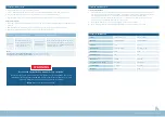
After the controller is powered on, when the switch points to ON, the machine is powered on, and the LCD displays: given rotating
speed, operating current, input voltage, operating status, whether “output rotating speed” is locked, failure interface and other
specific interface information as follows. Note: Interface is preset to English.
In the standby state, long press the knob (more than 2 seconds) to enter the ‘setting interface’. The setting interface functions are
as follows:


