

Model TE-703/704
Technical Information
TI.703/704-03
PIPE TEMPERATURE SENSORS
Page 3 of 4
RoHS
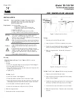
CHECKOUT
Allow the sensor to stabilize in (or against) the pipe for a minimum of five
minutes before taking a resistance measurement.
1. Disconnect the sensor lead wires from the controller.
2. Connect an ohmmeter across the lead wires.
3. Ensure that nominal resistance measurements are in accordance
with the resistance/temperature curves. (Refer to
Tables 1
& 2
.
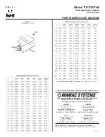
For complete
Resistance vs. Temperature
tables, please refer to
TI.700-11
- Temperature Sensor section.)
4. Reconnect sensor lead wires to the controller.
5. Check operation of the complete control system.
Figure 3
- Installing the TE-704-B, TE-704-C, or TE-704-D Sensor
MAINTENANCE
Regular maintenance of the total system is recommended to
assure sustained optimum performance.
FIELD REPAIR
None. Replace with a functional unit.
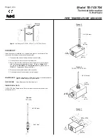
DIMENSIONAL DATA
TE-703/704 Pipe Temperature Sensors dimensions shown in inches and
millimeters (mm).
Figure 4
TE-703-A
Figure 6
TE-703-C & TE-703-D
Figure 5
TE-703-B
Figure 7
TE-704-B
1/4" (6.3 mm)
9/16" Hex
1/4" (6.3 mm)
1/4" (6.3 mm)
2.00"
(50 mm)
1.20"
(30 mm)
1.20"
(30 mm)
2.50"
(62 mm)
2.50"
(62 mm)
2.00"
(50 mm)
4.00"
(100 mm)
5.00"
(124 mm)
2.50"
(62 mm)
2.00"
(50 mm)
3.50"
(90 mm)
4.30"
(110 mm)
Sensing
element
Pipe
clamps
Pipe


