

Model TE-703/704
Technical Information
TI.703/704-03
PIPE TEMPERATURE SENSORS
Page 2 of 4
RoHS
Mount the Immersion Sensor:
Refer to
Figures 4, 5 & 6
for mounting
dimensions.
1.
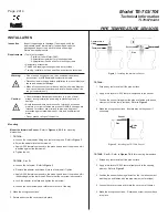
TE-703-A:
a. Loosen the compression fitting and remove the probe. Refer to
Figure 1
.
b. Screw the adapter into the thermowell.
c. Apply A-505 thermal compound to the probe tip and insert the probe until it
is seated against the thermowell.
d. Tighten the nut.
TE-703-B, C, or D:
a. Loosen the set screw. Refer to
Figure 1
.
b. Remove the adapter and thread it into the thermowell. Tighten.
c. Apply A-505 thermal compound to the probe tip and insert the probe until it
is seated against the thermowell. Ensure that the set screw is accessible.
d. Lock the adapter into place and tighten the set screw.
e. Loosen the cover screws and rotate the cover out of the way.
2. Make the wiring connections.
3. Rotate and screw the cover back into place.
Mounting
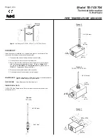
TE-704-A:
1. Scrape any rust or scale off the pipe surface.
2. Apply a thin layer of A-505 thermal compound to the sensor.
3. Position the sensor flat against the pipe and fasten with a hose
clamp or
nylon ties (not provided).
Refer to
Figure 2
.
4. Make the wiring connections. Insulate around the sensor if
necessary.
TE-704-B, C, or D:
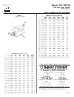
Refer to
Figures 7 & 8
for mounting dimensions.
1. Scrape any rust or scale off the pipe surface.
2. Apply a thin layer of A-505 thermal compound to the sensing
element. Refer to
Figure 3
.
3. Position the sensor’s sensing element so that it makes contact
with the pipe and fasten with two pipe clamps (
not provided
).
4. Loosen the cover screws and rotate the cover out of the way.
5. Make the wiring connections. Rotate and screw the cover back
into place.
Figure 1
- Installing the Immersion Sensor
Figure 2
- Installing the TE-704-A Sensor
Inspection
Requirements
INSTALLATION
Inspect the package for damage. If damaged, notify the
appropriate carrier immediately. If undamaged, open the
package and inspect the device for obvious damage.
Return damaged products.
•
Do not use on oxygen service, in an explosive/hazardous
environment, or with flammable/combustible media.
•
Disconnect power supply before installation to prevent electrical
shock and equipment damage.
•
Make all connections in accordance with the job wiring diagram
and in accordance with national and local electrical codes. Use
copper conductors only.
•
Use electrostatic discharge precautions (e.g., use of wrist
straps) during installation and wiring to prevent equipment
damage.
•
Avoid locations where severe shock or vibration, excessive
moisture or corrosive fumes are present. NEMA-4 housings are
intended for outdoor use primarily to provide a degree of
protection against wind-blown dust, rain, and hose-directed
water.
•
Do not exceed ratings of the device.
•
Tools (
not provided
)
- Digital Volt-ohm Meter (DVM)
- Appropriate screwdriver for mounting screws
- Appropriate drill and drill bit for mounting screws
•
Appropriate accessories
•
Two #8 self-tapping mounting screws (
not provided
)
•
Training:
Installer must be a qualified, experienced technician.
Warning:
Caution:
Set screw
Thermowell
Pipe
Compression
fitting
Thermowell
Thermowell
Pipe
Nylon
tie
Sensor


