background image

Damage to underwater gear
caused by shallow water
maneuvering is not covered by
your warranty. 

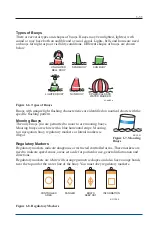
Warning Markers

Learn to recognize the different buoys and day
markers; they are used as the signposts of the
waterways identifying navigable routes and water
hazards. It is a good idea to ask local authorities about
hazard areas and if they are marked. Stay within
boundaries and clear of hazards.

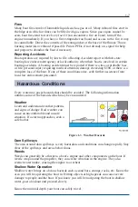
Figure 1-4. Diver Down Flag

Carbon Monoxide

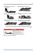
Carbon Monoxide (CO) is a colorless and odorless gas produced by all engines and fuel
burning appliances. Even with the best boat design and construction, plus the utmost care
in inspection, operation and maintenance, hazardous levels of CO may still be present in
accommodation spaces under certain conditions. To reduce CO accumulation, always
ventilate the boat interior and avoid boating situations which cause increased exposure.

The boat owner, as well as all boat occupants, must ensure that they understand the
dangers of carbon monoxide and comply with all safety recommendations/requirements.
No one should be allowed to stand or sit in any area of the boat that is not a designated
seat while the boat is running.

It is the responsibility of the boat owner and occupants of the boat to understand and
comply with all warning labels and safety recommendations/requirements.

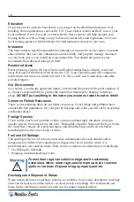
EXTREME HAZARD – Carbon monoxide gas (CO) is colorless,
odorless and extremely dangerous. All engines and fuel
burning appliances produce CO as exhaust. Direct and
prolonged exposure to CO will cause BRAIN DAMAGE or
DEATH. Signs of exposure to CO include nausea, dizziness
and drowsiness. Sources of CO include:

1-8

KC-0250M

Summary of Contents for Boat 2014

Page 1: ...nents are added to the boat after the retail purchase unless specifically authorized by Malibu Boats LLC This includes components such as Surf Gates fins wedges etc Customer Name s Customer Signature...

Page 2: ...2 Notes...

Page 3: ...time without notice and without incurring any obligation Trademarks Malibu and The Malibu Logo are registered trademarks of Malibu Boats LLC Surf Gate is a trademark of Malibu Boats LLC Indmar is a re...

Page 4: ...ii Notes...

Page 5: ...2 50 Go Home Feature 2 50 Storage Areas 2 50 VTX Table Installation 2 52 Drain Plugs 2 53 Speedometer Pickup 2 54 Tilt Steering Wheel 2 54 Exhaust 2 55 Ventilation 2 55 Closed Cooling System 2 56 Opti...

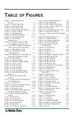
Page 6: ...uster 2 47 Figure 2 25 Seat Adjuster 2 47 Figure 2 26 Sundeck 2 48 Figure 2 27 Engine Access Hatch 2 48 Figure 2 28 Pivoting Head Ski Pylon 2 49 Figure 2 29 Swim Platform 2 49 Figure 2 30 Swim Step Pi...

Page 7: ...v Figure 4 4 GRV 4 7 Figure 4 5 ICV 4 7 Figure 4 6 Attwood Carbon Canister 4 7 Figure 4 7 Main Circuit Breaker 4 8 Figure 4 8 Battery Level 4 9 Figure 4 9 Battery Switch 4 11...

Page 8: ...vi Notes...

Page 9: ...ue to be our 1 priority CERTIFICATIONS STANDARDS NMMA Certification Your Malibu boat has been built to meet or exceed the standards set by the National Marine Manufacturers Association NMMA NMMA verif...

Page 10: ...oil Cooking fuels Cleaners paints and substances used for vessel repair Waste materials that result from wear of vessel components Lead from battery terminals and from other sources such as ballast or...

Page 11: ...f the boat owner and occupants of the boat to understand and comply with all warning labels and safety recommendations requirements General Precautions Your Malibu boat has been constructed to meet al...

Page 12: ...In an emergency situation you may have to resort to measures which are not commonly practiced Always assess the dangers of being in harm s way versus the protection of equipment Keep a sound mind dur...

Page 13: ...in a way that can and too often does lead to death That is why it is so important to the Coast Guard that in every circumstance where it can be avoided it is The boat owner as well as all boat occupan...

Page 14: ...ent by keeping waterways clean DO NOT put anything in the water you would not want to eat or drink Conserve Fishery Resources There is a tremendous drain on our fishery resources Over fishing and poll...

Page 15: ...environmental regulations that may govern your paint choice Contact your local boating authorities for information Cleaning Agents Household cleaners should be used sparingly and not discharged into...

Page 16: ...arged Figure 1 2 Fire Extinguisher 3 Navigation Lights Recreational boats are required to display navigational lights between sunset and sunrise and other periods of reduced visibility fog rain haze e...

Page 17: ...any of these conditions arise seek further assistance from local law enforcement personnel Hazardous Conditions Every waterway poses hazards that should be avoided The following information outlines...

Page 18: ...ces under certain conditions To reduce CO accumulation always ventilate the boat interior and avoid boating situations which cause increased exposure The boat owner as well as all boat occupants must...

Page 19: ...1 9 Figure 1 5 Carbon Monoxide Hazards KC 0461M...

Page 20: ...affected creating situations that can be very dangerous Federal and state laws prohibit operating a boat under the influence of alcohol and other drugs These regulations are actively enforced Impaire...

Page 21: ...are white with a blue horizontal stripe Mooring to a navigation buoy regulatory markers or lateral markers is illegal Figure 1 7 Mooring Buoys Regulatory Markers Regulatory markers indicate dangerous...

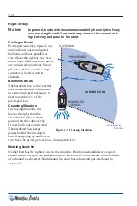
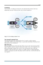
Page 22: ...and speed necessary to keep out of the way of the privileged boat Crossing Situation In crossing situations the boat to the right from the 12 o clock to the 4 o clock position has the right of way It...

Page 23: ...void collision Night Running Boats operating between sunset and sunrise hours vary by state must use navigational lights Nighttime operation especially during bad weather or fog can be dangerous All R...

Page 24: ...1 14 Notes...

Page 25: ...tandard Gauges The following gauges are included on all models It is important for the safe and proper operation of your boat to fully understand these gauges Malibu In Dash Graphical Display Figure 2...

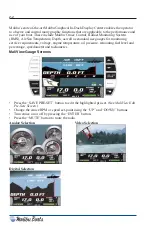
Page 26: ...standard use gauges for monitoring service requirements voltage engine temperature oil pressure remaining fuel level and percentage speedometer and tachometer MaliView Gauge Screens Press the SAVE PR...

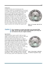
Page 27: ...may not be covered under your engine warranty Speedometer The Speedometer registers speed in miles per hour MPH The speedometer system consists of a thru hull paddle wheel speed sensor that records wa...

Page 28: ...eratures slow down immediately and turn off engine Continuing to operate the boat while the temperature is above normal operating parameters may cause serious damage to your engine Fuel The fuel gauge...

Page 29: ...ore operating again Do not continue to run engine if pressure is low If you do the engine can become so hot that the surrounding components could catch fire Notice Damage caused from neglected oil pro...

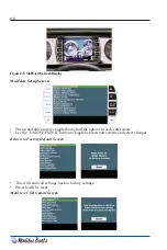
Page 30: ...n arrows toggle through all the options in each edit screen Use the ON OFF ENTER button to toggle between edit screens and select changes Return to Factory Default Screen This will return all settings...

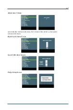
Page 31: ...2 7 Adjust Auto Volume Automatically increases decreases the volume of the stereo as boat speed increases decreases Depth Level Alarm Screen Speed Calibration Screen Wedge Setup Screen...

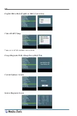
Page 32: ...nglish Metric Mode English or Metric Conversion Video ON OFF Setup Turns on or off all available video screens Gauge Diagnostic Mode Gauge Sweep Mode Test Current Software Version System Diagnostic Sc...

Page 33: ...s checked After enabling the SURF GATE you will need to calibrate the gates This process is automatic once it s started Just follow the instructions on the screen SETUP CRUISE GAUGES PRE SETS CRUISE M...

Page 34: ...or surfing on the right side of the boat Alert banner that a left or right surf button has been pressed Caution banner for over speed with a Surf Gate out The gate will automatically retract until spe...

Page 35: ...ss is located by the radio black box under the glove box If the MDG is turned off or there is no device connected the button will appear gray If MDG has a device connected or turned on the button will...

Page 36: ...devices The system can control what device is connected by either accepting or declining the connection Only one device at a time can be connected The HELP button will share additional information on...

Page 37: ...impossible to put together factory pre sets that work the same on every boat For this reason we chose a middle of the road setting and worked to create an easy method to modify the factory pre sets an...

Page 38: ...n or off in the setup screen Make sure you have a calibrated power wedge for correct operation Ballast bars will disappear when the sensor is not present The engine must be running for the wedge to mo...

Page 39: ...nue to press ENTER for all 20 spaces Power Wedge Edit Screen There are 10 different WEDGE settings Using the up and down buttons select the desired WEDGE setting 200 if fully stowed 100 if max wedge a...

Page 40: ...ballast level Use the up and down buttons to change the level The tank being edited is highlighted green Press ENTER to accept the change SAVE EXIT NO SAVE SAVE EXIT NO SAVE PRE SET EDIT SET POINT 20...

Page 41: ...ink Additional alarm parameters may be added The Indmar engine is equipped with the E Control New Engine Control Module with OBD M If the engine ECM activates an alarm you will ether see Engine Fault...

Page 42: ...edge is moving up past the wake zones The WEDGE FAULT STARBOARD ACTUATOR MAXED is a signal from the Lenco box indicating a starboard actuator failure or fault The WEDGE FAULT STARBOARD ACTUATOR AVERAG...

Page 43: ...ow see two lists Active 1 or Inactive 1 It is the 1 or 0 that is important here If the fault is currently Active a real serious problem you will see a 1 to the right of active If the problem was a mom...

Page 44: ...s until the desired water depth is set The system is set to default at 2 ft Once this is completed press E Enter to return to main menu Notice The Depth graphical display only displays the bottom of t...

Page 45: ...on in gap for proper operation Going above or below gap line will disengage cruise current throttle position Operation of Malibu Precision Pro Speed Control Adjust set points by pressing up and down a...

Page 46: ...window the Precision Pro Speed Control System will hold the desired target speed If the small square is to one side of the target window the computers will have limited authority to adjust the throttl...

Page 47: ...d NOTES The gap appears when the engine has activated cruise and has control of the throttle The cruise must be turned on or off when the actual speed is below the set point The cruise will only hold...

Page 48: ...d the system will automatically enter a DECEL mode and slowly return the engine throttle to the set RPM When the system has engaged the throttle bar will turn green Keep the arrow in the gap to allow...

Page 49: ...he foil all the way up The Power Wedge is intended to be deployed down prior to pulling up the rider it will not deploy above 10 MPH Boats not equipped with PW must have the Power Wedge mode switched...

Page 50: ...lowest position the wake is comparable to approximately 400 lb of ballast in the rear of the boat Your Malibu can be trailered or launched with the PW down but make sure to raise it once you are on th...

Page 51: ...em See your dealership immediately to locate the problem Figure 2 13 Circuit Breaker Panels Switches Indicators Figure 2 14 Horn Button and Power Button For boats equipped with Malibu Touch Command th...

Page 52: ...VIGATION screen Malibu Boats equipped with the Malibu Touch Command are also equipped with a remote ignition key switch This remote key is provided for emergency use only Should the CAN communication...

Page 53: ...engine will crank Press the STOP button to stop the engine without turning off the dash The button must be held for a second before the engine will shut down The CHANGE button will allow the user to...

Page 54: ...SWITCH screen Press the FILL ALL or DRAIN ALL buttons to control all the tanks at once If you press the ALL OFF or the OFF button the boat will stop the FILL ALL or DRAIN ALL process The MLS screen a...

Page 55: ...be displayed in approximate location of the light Optional lights can be added or removed in the setup screen located on the SWITCH screen The buttons will light up yellow when active The tower light...

Page 56: ...ight Optional heater switch can be added or removed in the setup screen If the heater is removed the button will turn into an auxiliary output to be used if needed The setup button contains some of th...

Page 57: ...up mode desired Press ENTER button to access the mode highlighted Pressing the ENTER button will activate the RESET TO FACTORY SETTINGS Doing the reset is a good idea after every new software update Y...

Page 58: ...tTouch mem file The update will not work unless the file is named SmartTouch mem The system will reset automatically when complete The UPDATE can also be done by just turning off and on the power with...

Page 59: ...Use the UP and DOWN buttons to highlight the setup mode desired Press ENTER button to access the mode highlighted Pressing the ENTER button will activate the BACKLIGHT DIM LEVEL mode Once activated us...

Page 60: ...etup mode desired Press ENTER button to access the mode highlighted Pressing the ENTER button will activate the SETUP OUTPUTS mode Turning on and off ballast will change the appearance of the MLS scre...

Page 61: ...nd MaliView system Use the UP and DOWN buttons to highlight the setup mode desired Press ENTER button to access the mode highlighted Pressing the ENTER button will activate the SETUP LIGHTS mode Turni...

Page 62: ...nd DOWN buttons to highlight the setup mode desired Press ENTER button to access the mode highlighted Pressing the ENTER button will activate the NAVIGATION mode Refer to the NAVIGATION manual for com...

Page 63: ...o date and adjust and troubleshoot the Touch Command MaliView system Use the UP and DOWN buttons to highlight the setup mode desired Press ENTER button to access the mode highlighted Pressing the ENTE...

Page 64: ...nsor in the bilge area and will turn on automatically whenever 2 in or more of water is detected The bilge pump is wired directly to the battery This circuit can be identified by an inline fuse from t...

Page 65: ...or Lights This switch is used to activate the interior lights The interior lights include lights in the gunnels storage compartments and dashboard and optional underwater transom lights if equipped Na...

Page 66: ...ing the MLS CENTER button will toggle the POWER module output and MUX display from OFF to FILL to OFF to DRAIN and back to OFF again Pressing the MLS FRONT button will toggle the POWER module output a...

Page 67: ...ns 4 Once an function icon is selected hold down the button for 3 seconds to lock it in 5 After lock in return to CHANGE edit mode screen Delete Mode 1 Press button 1 YES to enter DELETE mode or 2 NO...

Page 68: ...4 Once an function icon is chosen hold down the button for 3 seconds to INSERT that function icon 5 After insertion all functions icons should shift to the right 6 After insertion return to INSERT ed...

Page 69: ...there is an indicator light that illuminates when the neutral shift lock is engaged The throttle control shown in Figure 2 20 does not have the neutral shift lock activation button When you push the...

Page 70: ...f the throttle control refer to the separate instructions located in the information packet shipped with your boat Steering System It is important that you get the feel of your Malibu boat s steering...

Page 71: ...ft side of the driver s seat Pull lever outward and adjust seat as needed Lumbar Support The driver s seat is equipped with a Lumbar Support To adjust locate the twist knob located on the left side of...

Page 72: ...access hatch is located behind the rear observers seat on the V Drive Access allows the ability to service the engine for required maintenance and for additional storage on both sides of the engine En...

Page 73: ...slide back on the platform To replace reverse these steps Be sure the latches are securely fastened DO NOT use the boarding platform for any other purpose than boarding the boat or preparation of ent...

Page 74: ...can cause burns if touched The light can stay hot for an extended period of time after it has been turned off Go Home Feature The Go Home feature will enable the navigation lights bow and tower to il...

Page 75: ...e storage of your ski items Figure 2 33 Lockable Transom Storage Glove Box Storage Located on the port side of the boat above the observers seat for easy access and storage This small area can be used...

Page 76: ...ort pole from under the port side pull up cushion 2 Slide the base of the pole into the mounted receiver 3 Place the table receiver onto the top of the pole Reverse the process to stow the table away...

Page 77: ...plugs are secure prior to launching your boat Damage caused as a result of these plugs not being installed will not be covered under your Malibu warranty Bilge Drain Plug s A T handled brass bilge dr...

Page 78: ...This information is transferred to the dash computer and a computer program converts information which is transferred to the speedometer gauge See Troubleshooting section of this manual for basic mai...

Page 79: ...hose clamps being careful not to crimp the hose See your Malibu dealer for parts and or service Notice The Monsoon and L96 engines equipped with the ETX Catalyst Exhaust Manifolds may produce an unus...

Page 80: ...a heater you will find an ON OFF accessory switch located on the dash panel Located at the base of the observer seat walkway is a snorkel tube that can be pulled out and directed wherever you like wi...

Page 81: ...ey can be turned to the left if you will not be running the boat Some systems if equipped will have an optional remote pad located at the back of the boat either in the passenger area or exterior tran...

Page 82: ...dio screens the left and right buttons will respond to the label directly inside the button For example the CRUISE button is now the BACK TO VIPER button in all PAGE 1 screens in every mode Fosgate FM...

Page 83: ...2 59 Fosgate USB DRIVE Radio Screens...

Page 84: ...2 60 SIRIUS Radio Screens...

Page 85: ...2 61 Fosgate IPOD Radio Screens...

Page 86: ...To use this ability the radio video screen with button needs to be enabled in the MEDIA SETUP screen in SETUP This mode will bring up buttons on the side for 5 seconds These buttons describe what eac...

Page 87: ...is is the POV RF module It is connected to the system using a gauge connector located with the other gauge connections Make sure the video output from the POV is going into the Video 2 input on the Vi...

Page 88: ...has the standard RCA cables as an output it will play through the stereo AUX mode and onto the screen in Video 2 We provide the left right audio to mini adapter that came in your boat bag and the vide...

Page 89: ...g the Navigation system the screen below is the first screen that is displayed Main Map Screen When entering the Navigation area this is the first screen that comes up Each section of the screen is hi...

Page 90: ...2 66 Navigation Menu Above is the main navigation menu screen From here the operator can get to any area of the navigation system Pressing the ENTER button will display the MAP screen...

Page 91: ...MAP on the entire screen or show gauge information along the right hand side of the display Underneath the words MAP VIEW are the words FULL and GAUGE The word that is highlighted indicates how the MA...

Page 92: ...NT toward the top left of the screen are the words BEARING and NORTH The word that is highlighted indicates how the MAP screen will be oriented Pressing the UP RIGHT arrow will cause the highlight to...

Page 93: ...2 69 Select Course Creating a New Course...

Page 94: ...appear showing the available waypoint options Use the arrows to highlight the desired waypoint and press ENTER The map screen will be shown again with the waypoint in the location that the cursor was...

Page 95: ...2 71 Select Auto Course Creating a New Auto Course...

Page 96: ...l appear Your location is the boat image in the screen to the left it is within the blue box The navigation software will track your movements until the STOP COURSE option is selected NOTE Be sure to...

Page 97: ...ughout the various screens From the Navigation Menu screen press the DOWN RIGHT arrow to adjust the filters The screen above shows the objects that may be available to display If there is an object th...

Page 98: ...access the GPS STATUS screen The GPS STATUS menu allows the operator to view up to a 16 position satellite signal strength graph on the right side of the display and a 4 point compass graphic showing...

Page 99: ...2 75 Setup From the Navigation Menu screen press the DOWN LEFT arrow to access the SETUP menu The SETUP menu allows the operator to adjust view and configure the navigation system through eight menus...

Page 100: ...NTER button The screen below will appear Using the arrows UP DOWN changes between the low high scale Normal Mode High Contrast and Night View The LEFT RIGHT arrows control the slide on the Low to High...

Page 101: ...ht the TRANSPARENCY LEVEL and press the ENTER button The screen below will appear Using the arrows UP DOWN changes between the transparency scale and the EXIT The LEFT RIGHT arrows control the slide o...

Page 102: ...ap while operating the menu features Highlight the GPS SETUP and press the ENTER button The screen below will appear Using the arrows UP DOWN changes between the Coordinate styles and WAAS status opti...

Page 103: ...MAP and press the ENTER button The screen below will appear The GPS STATUS menu allows the operator to view up to a 16 position satellite signal strength graph on the right side of the display and a 4...

Page 104: ...de of the screen Highlight the SYSTEM SETUP and press the ENTER button The screen below will appear Any of the options listed above can be displayed in the gauge area of the MAP screen Only seven item...

Page 105: ...H LEVEL SETUP and press the ENTER button The screen below will appear The options listed above will change how the waterways are to be displayed on the MAP screen Depending on which setting is chosen...

Page 106: ...ween Nautical Miles and Miles Highlight the SYSTEM UNITS SETUP and press the ENTER button The screen below will appear The options listed above will change how the speed and distance are to be display...

Page 107: ...ER button The screen below will appear The options listed above will change the color of that feature that is to be displayed on each screen Highlight the desired option and press ENTER This will disp...

Page 108: ...2 84 Exit Setup Highlighting the EXIT SETUP and pressing ENTER will bring the display back to the MENU screen...

Page 109: ...AP mode shows the Course name Next Waypoint and Destination COMPASS mode shows the compass rotating with the heading always at the top of the screen This option also shows the Course name Next Waypoin...

Page 110: ...OFF Will leave a trail in the direction of where your last waypoint was ADJUST NOTIFY BAND Pressing the UP RIGHT arrow brings up a box that allows the setting of the notify distance to the next POI Wh...

Page 111: ...the accessory switch panel and have a 10 amp circuit breaker The docking lights use LED bulbs which cannot be replaced Illusion G3 The Illusion G3 has a solid foundation of billet aluminum bases and b...

Page 112: ...allowed to fall Towers are configured from the factory with shocks based on the factory installed components If ANY additional components are mounted to the tower after the boat leaves the factory it...

Page 113: ...use adverse handling conditions It is recommended that you put the Wedge unit in the UP position if you will be traveling over these speeds Scarpa Suppression Plate SSP The Scarpa Suppression plate is...

Page 114: ...2 90 Notes...

Page 115: ...ear and trailer does not exceed the GVWR Verify tire pressure for load capacity Notice Consult your trailer dealer for other state regulations concerning brakes lighting and other equipment options Hi...

Page 116: ...to consider Bow Tie Downs A bow stop to hold the front of your boat in place is located on the winch stand It should be positioned so that the winch line pulls straight and is parallel to the trailer...

Page 117: ...ater and stop Be sure to properly secure your vehicle Prepare for placing the boat in the water by removing any tie down straps disconnecting tail light connections and attaching a line to the bow eye...

Page 118: ...splayed at various locations throughout your new Malibu to point out safety hazards It is important that you take the time to locate these labels Do not remove or cover warning labels Replace when ill...

Page 119: ...Warning Label Locations Refer to the diagrams below for the location of each label 3 5...

Page 120: ...nt unsafe operation Care must be taken to ALWAYS avoid creating a bow heavy or any other unsafe condition If in doubt contact an authorized Malibu service center Do not allow anyone to sit on the back...

Page 121: ...boat Gasoline vapors are heavier than air and will develop in the lower cavities of the boat such as the bilge Do not allow the fuel tank to empty completely during operation Doing so may damage the...

Page 122: ...otive style Audible Click Hinged fuel cap Vent system operational at all angles with full tank of fuel Diurnal Emissions Control System Key Components Deck Fill Inlet control valve between deck fill a...

Page 123: ...n a Malibu Factory Trained and Certified Technician Special tools and training are required to service this fuel system Pay close attention to the information regarding the break in period listed in y...

Page 124: ...before returning to operation Pressing the ENTER button on the display will silence the alarm for five minutes Following is a list of monitored functions that can activate the alarm Engine Oil Alarm R...

Page 125: ...e re engaging the transmission by depressing the knob Figure 3 8 Throttle Positions When engaging the transmission from neutral to either forward or reverse you must pull up on the safety collar locat...

Page 126: ...effect is to steer the boat back and forth in an attempt to compensate for wandering Invariably the compensation will result in oversteer and only worsen the effect Keep the steering wheel in the cen...

Page 127: ...d to starboard when going backward At high speed this effect is usually unnoticed but at slow speed especially during backing it can be powerful For this reason many veteran boaters approach the dock...

Page 128: ...es when docking Approach docks with the starboard side of the boat if possible Come to a stop a short distance from the dock then proceed slowly Have fenders mooring lines and crew ready Observe how t...

Page 129: ...ed Operation A great deal of caution must be exercised when operating any boat at high speeds This is particularly true during turns Gradual turns can be completed at high speed by a competent driver...

Page 130: ...ow communication between the skier and the driver of the boat A copy of these signals can be found for review at your local Malibu dealership or by contacting USA Water Ski at 863 324 4341 or online a...

Page 131: ...rously Fasten the towline as far forward as possible on the upwind or up current side of the boat being towed Fastening it to the stern will restrict maneuverability Attach the line to the stern lifti...

Page 132: ...act your dealer otherwise adverse handling and top speed characteristics may be experienced The prop is identified by two numbers i e 13 x 14 and material identification such as brass or stainless ste...

Page 133: ...is seating properly 3 Wedge a piece of 1 x 4 wood between the propeller blade and the port side of the strut and rudder 4 Install a new nylon locknut and torque the nut to maximum of 30 ft lbs 40 7 N...

Page 134: ...g the softer metal will deteriorate and erode much faster than the other metals in the boat Inspect the anode periodically and replace as needed Consult your local Malibu dealer for this part Saltwate...

Page 135: ...e are no products available to us that are mildew proof Therefore we also recommend that you dry the upholstery thoroughly at the end of each day s boating activity to prevent mildew which will rot th...

Page 136: ...and could damage the surface of your interior Common stains and steps to treat Type of Stain Step 1 Step 2 Step 3 General care A B Dirt buildup A B Ballpoint ink B A Chewing gum B A Coffee tea chocola...

Page 137: ...dware permanently Always follow cleaning by applying a high quality metal polish or automotive wax after cleaning Test products in an inconspicuous area before applying to the complete surface especia...

Page 138: ...at you leave your boat moored for long periods of time If your boat will be moored in fresh water or saltwater for extended periods of time you should do the following 1 Haul out and clean your boat r...

Page 139: ...It is recommended that only a trained service technician perform this maintenance due to the complications that can arise from an improperly balanced prop shaft engine alignment Damaged caused from l...

Page 140: ...es can cause damage to the engine and fuel system DO NOT mix MTBE and ethanol Drain your tank or use up as much of the old fuel as you can before making the switch to E10 Once done do not go back to M...

Page 141: ...ns be inspected annually for tightness Figure 4 2 P Trap and Deck Fill Figure 4 3 FLVV Figure 4 4 GRV Figure 4 5 ICV Figure 4 6 Attwood Carbon Canister Replacement Fuel System Components Should any pa...

Page 142: ...tly to the battery with proper overload protection Boat Alarms Malibu boats are equipped with sensors that constantly monitor various functions of the boat Certain functions if outside of pre determin...

Page 143: ...o 1 2 in above the plates is sufficient If needed fill with distilled water Some batteries are sealed and this process is not necessary Read directions when applicable Electrical Distribution Battery...

Page 144: ...s the starting and house circuits to reduce the chance of fully discharging both batteries and protect on board electronics from engine starting voltage sages and spikes The Combine Batteries Position...

Page 145: ...imate upgrade it prevents cranking voltage spikes from causing any problems with the onboard computer network With the VSR equipped systems you will notice that when you turn on the key the stereo wil...

Page 146: ...on these components especially for use in areas of or in proximity to salt brackish water Pitting corrosion or oxidation is not covered under warranty Pitting is not the same as separation Bilge The b...

Page 147: ...Turn engine off Consult your local dealer for correct procedure To be completed when boat is put on trailer or resting cradle Remove bilge T handle and transom drain plug immediately after removing t...

Page 148: ...laps Charge and install battery in boat Follow all safety precautions associated with changing batteries De winterize engine using engine manufacturer s specifications Check propeller shaft alignment...

Page 149: ...most likely event to the least likely To correct a problem first determine what the problem is Start with the first cause and eliminate the possibility of each until the problem is corrected Because...

Page 150: ...the battery Ignition problems See your dealer Engine misses or Fouled spark plugs Replace spark plugs idles rough Loose or defective high Tighten or replace the high tension leads tension leads Plugg...

Page 151: ...peller Replace the propeller Misaligned propeller shaft Check the alignment See coupling your dealer for proper realignment Bent propeller shaft See your dealer Electrical problems Open circuit breake...

Page 152: ...but made from fibrous glass Glass fiber forms include cloth yarn mat milled fibers chopped strands roving and woven roving GELCOAT A surface either colored or clear providing a cosmetic enhancement a...

Page 153: ...ranty W 1 Malibu Exclusive Adjustable Rudder System 3 19 Miscellaneous 4 12 Motorbox Cover 2 47 N Navigational Lights 2 50 O Operation 3 1 Operation by Minors 1 10 Optional Equipment 2 56 P Passenger...

Page 154: ...ck brake fluid level if applicable LAKE TEST ____ 1 Perform Diacom data list scan ____ 2 Check PROM ID and record in customer file ____ 3 Check fuel pressure and log reading ____ 4 Verify oil levels e...

Page 155: ...e warranty details that follow for complete terms conditions and limitations In addition to the Malibu Limited Warranty your boat also comes with other limited warranties provided by the engine and tr...

Page 156: ...xclusion may not apply to you Who Is Covered Under the Malibu Boats Limited Warranty Subject to all other terms conditions and limitations 1 original owners of the boat and 2 second owners of the boat...

Page 157: ...Limited Warranty Coverages Base Limited Warranty For a period of thirty six 36 months beginning on the date the boat is purchased by the first retail purchaser through an authorized Malibu Boats sales...

Page 158: ...or osmosis as well as damage due to in water storage without proper barrier coat and bottom paints The Gelcoat Limited Warranty is Not Transferable Lifetime Hull Limited Warranty For the life of the b...

Page 159: ...rom normal wear and tear Conditions resulting from use of the boat for anything other than recreational purposes Manufacturing variations or imperfections in cosmetic convenience or aesthetic componen...

Page 160: ...s looms or other components of the boat s electrical or fuel systems Determination by any state or federal entity or private insurance carrier that the boat is a total loss or fit only for salvage Thi...

Page 161: ...strongly recommends that you follow all of the instructions in the boat s operating manuals including if applicable any accompanying maintenance or service schedules Because questions may sometimes ar...

Page 162: ...ady have been reviewed by the service manager or foreman request to speak with the facility s general manager or owner Second if your concerns are not resolved to your satisfaction by the representati...

Page 163: ...per Attwood installation instructions and The component cannot have been altered or abused by Boat Company or its customers Warranty Terms for Components Attwood warrants that any Attwood Fuel System...

Page 164: ...Notes W 10...
Reviews: