


9
Fig 2.7.
200 MHz, 400MHz and 1.3 GHz antennas. Lengths are 455, 230 and 90 mm respectively.
Several separate transmitter and receiver antennas are combined into one single antenna array unit
mounted in a box suitable for field surveys. 200 and 400MHz boxes are designed to include also the
control unit.
2.4 Positioning systems
The antenna array must be positioned with a high level of accuracy through out the survey. A precise
control of the geometry is an absolute prerequisite to make the resulting 3D radar picture correct and
reliable. Centimetre accuracy is needed over the whole investigation site. The MIRA system can be
positioned by using a RTK GPS system or a self-tracking laser theodolite, a so called total station. A
prism or a GPS rover antenna is attached to the array box, and a radio link transfers the positioning
data from the GPS base station or Total station back to the acquisition laptop. See Fig. 2.8.
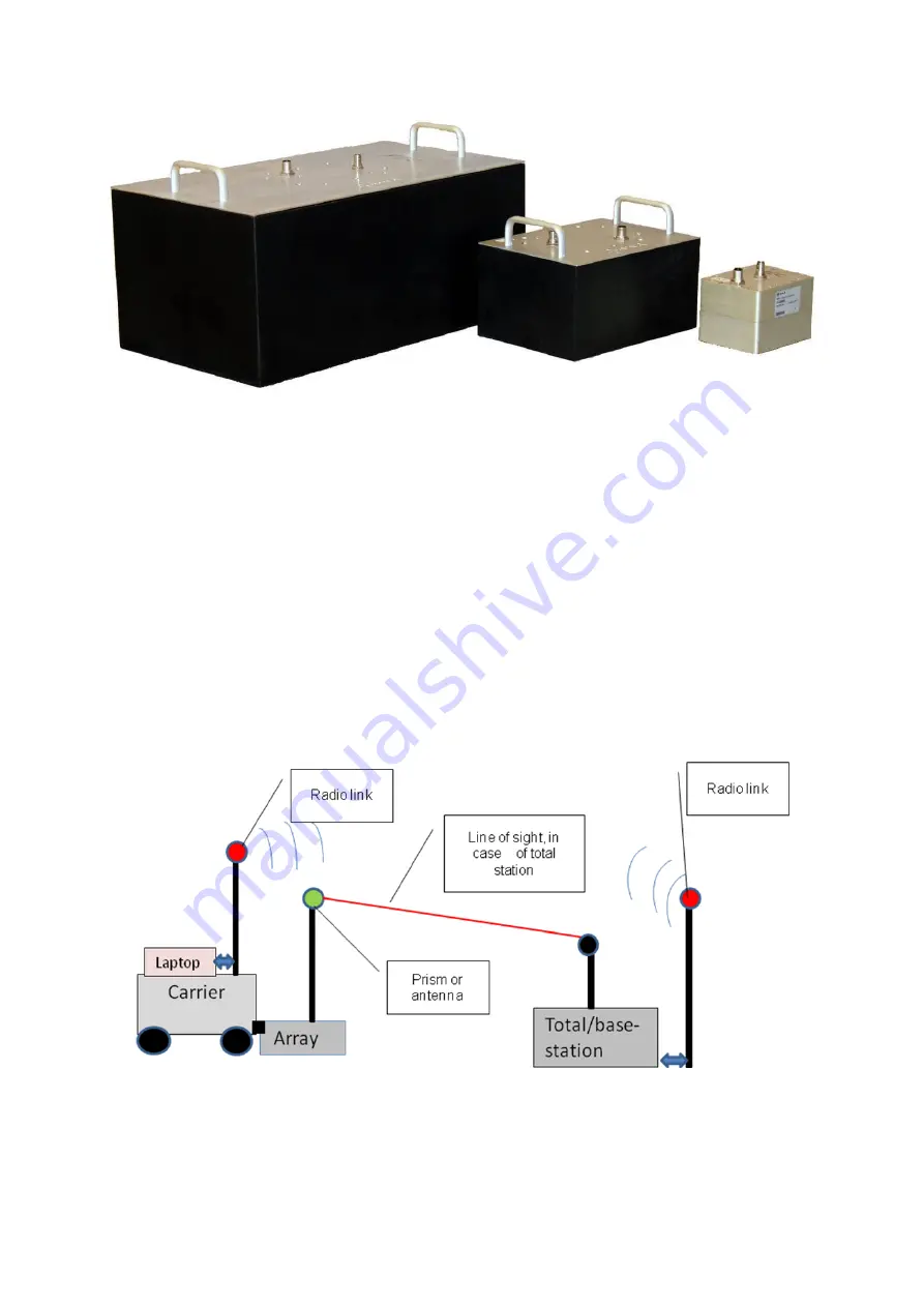
Fig 2.8
Principal layout of the positioning system.
With the layout in Figure 2.8 the operator of the carrier vehicle will be able to control/monitor both the
operation of the radar system as well as the positioning system while steering the carrier vehicle.


