

P 9/ 10
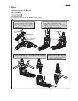
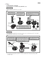
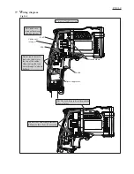
Wiring of Field lead wire
Rib C
Rib D
Rib A
Rib B
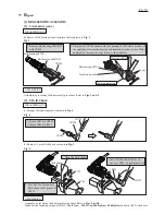
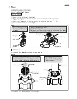
Wiring of Earth lead wire
Fig. D-2
Fig. D-3
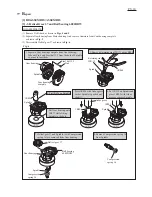
arrow
slit
Terminal
Noise suppressor
Lead wire
holders
Rib E
Rib D
1. Insert terminal of the
earth lead wire (white)
into the slit near the
arrow showing the
rotating direction.
3. Fix the lead wire (white)
in Lead wire holders.
Route Field lead wire (white)
between Rib A and Rib B.
Route Field lead wire (black)
between Rib C and Rib D.
Route Field lead wire (white)
through the groove.
Route Field lead wire (black)
through Lead wire holders.
2. Route the Lead wire (white)
between Rib D and Rib E.
Note
: Do not route the earth lead wire (white) over the
top of the cables when routing the lead wires
through Lead wire holders.
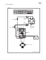
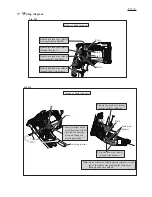
W
iring diagram