

R
epair
P 5/ 10
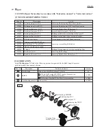
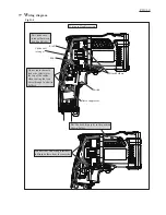
Retaining ring
WR-12
Spindle
[3] DISASSEMBLY/ASSEMBLY
DISASSEMBLING
Fig. 6
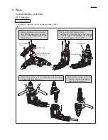
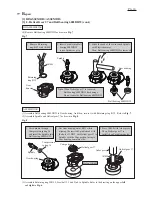
[3] -3. Helical Gear 37 and Ball bearing 6002DDW
(1) Remove Drill chuck as drawn in
Figs. 4 and 5
.
(2) Separate Gear housing from Motor housing. And remove Armature from Cam housing complete
as drawn in
Fig. 2
.
(3) Disassemble Helical gear 37 as drawn in
Fig. 6
.
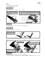
1. Separate Cam housing complete from Gear housing.
Take out Pin 4 and Steel ball 3.5 from the hole of Spindle
so as not to lose them.
2. Remove Retaining ring WR-12 with 1R004.
Cam housing
complete
Gear housing
Steel ball 3.5
Pin 4
1R004
3. Put Gear housing onto
1R037 while fitting
Spindle to the hole.
Spindle
1R037
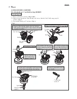
1R026
4. Put 1R026 on Spindle.
5. Press 1R026 with Arbor press
so that Spindle is pushed out
slightly.
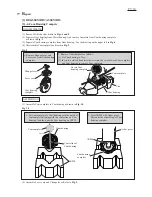
6. Put 1R238 on Spindle and
press 1R283 with Arbor
press to remove Spindle.
7. Helical gear 37 and Spindle (with Compression
spring 16) are removed from Gear housing.
8. Remove Compression spring 16
from Spindle.
1R026
Arbor press
1R283
Spindle
Spindle
1R037
1R037
Helical gear 37
Ball bearing
6002DDW
Gear housing
Spindle
Compression
spring 16
Compression
spring 16