

P 4/ 10
[3] DISASSEMBLY/ASSEMBLY
[3] -1. Armature (cont.)
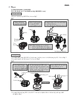
DISASSEMBLING
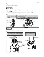
[3] -2. Drill Chuck
ASSEMBLING
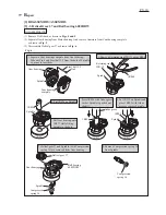
(2) Remove Ball bearings from Armature shaft as drawn in
Fig. 3
.
Assemble by reversing the disassembly procedure. Refer to
Figs. 3 and 2.
1. Remove Ball bearing 608DDW
with 1R269.
2. The claws of 1R269 cannot hold Ball bearing 607ZZ firmly because of
the small gap between the bearing and insulation washer. So use Water
pump pliers to secure the legs firmly as shown below.
Water pump pliers
Claws of 1R269
Fig. 3
Ball bearing 607ZZ
Insulation washer
Legs
Ball bearing 608DDW
1R269
Ball bearing 607ZZ
R
epair
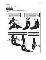
DISASSEMBLING
1. Attach 1R224 to 1R223.
2. Attach 1R298 to R224.
(1) Arrange the repairing tools as drawn in
Fig. 4.
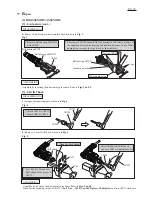
(2) Remove 13 mm Drill chuck as drawn in
Fig. 5
.
Fig. 4
Fig. 5
1R224
1R223
R139
1R298
1R298
1R223
Vise
Drill chuck
1. Open the Drill chuck.
2. Fix 1R139 to Vise and set
Drill chuck to the groove of
1R139.
3. Insert 1R298 into Drill chuck
and turn 1R223 counterclockwise.
ASSEMBLING
Assemble by reversing the disassembly procedure. Refer to
Figs. 5 and 4
.
Note
: Set the fastening torque of 1R223 to
26.0 N.m ~ 30.10 N.m
(
265 Kgfcm ~ 306 Kgfcm
) and turn 1R223 clockwise.