background image

used. 

• 

Be sure to identify safety measures to protect the 
operator that are based on an estimation of 
exposure in the actual conditions of use (taking 
account of all parts of the operating cycle such as 
the times when the tool is switched off and when it 
is running idle in addition to the trigger time). 
 

ENH101-15 

For European countries only 

EC Declaration of Conformity 

We Makita Corporation as the responsible 
manufacturer declare that the following Makita 
machine(s): 

Designation of Machine:   
Power Planer 
Model No./ Type: MT191 
are of series production and 

Conforms to the following European Directives: 

2006/42/EC 

And are manufactured in accordance with the following 
standards or standardised documents: 

EN60745 

The technical documentation is kept by our authorised 
representative in Europe who is:   

Makita International Europe Ltd. 
Michigan Drive, Tongwell, 
Milton Keynes, Bucks MK15 8JD, England 
 

23.11.2010


000230 

Tomoyasu Kato 

Director 

Makita Corporation 

3-11-8, Sumiyoshi-cho, 

Anjo, Aichi, 446-8502, JAPAN 


GEA010-1 

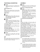
General Power Tool Safety 
Warnings 


WARNING Read all safety warnings and all 

instructions.

 Failure to follow the warnings and 

instructions may result in electric shock, fire and/or 
serious injury. 

Save all warnings and instructions for 
future reference. 

GEB010-4 

PLANER SAFETY WARNINGS 

1. 

Wait for the cutter to stop before setting the 
tool down.

 An exposed cutter may engage the 

surface leading to possible loss of control and 
serious injury. 


2. 

Hold the power tool by insulated gripping 
surfaces only, because the cutter may contact 
its own cord.

 Cutting a "live" wire may make 

exposed metal parts of the power tool "live" and 
could give the operator an electric shock. 

3. 

Use clamps or another practical way to secure 
and support the workpiece to a stable platform.


Holding the work by hand or against your body 
leaves it unstable and may lead to loss of control. 

4. 

Rags, cloth, cord, string and the like should 
never be left around the work area. 

5. 

Avoid cutting nails. Inspect for and remove all 
nails from the workpiece before operation. 

6. 

Use only sharp blades. Handle the blades very 
carefully. 

7. 

Be sure the blade installation bolts are 
securely tightened before operation. 

8. 

Hold the tool firmly with both hands. 

9. 

Keep hands away from rotating parts. 

10. 

Before using the tool on an actual workpiece, 
let it run for a while. Watch for vibration or 
wobbling that could indicate poor installation 
or a poorly balanced blade. 

11. 

Make sure the blade is not contacting the 
workpiece before the switch is turned on. 

12. 

Wait until the blade attains full speed before 
cutting. 

13. 

Always switch off and wait for the blades to 
come to a complete stop before any adjusting. 

14. 

Never stick your finger into the chip chute. 
Chute may jam when cutting damp wood. 
Clean out chips with a stick. 

15. 

Do not leave the tool running. Operate the tool 
only when hand-held. 

16. 

Always change both blades or covers on the 
drum, otherwise the resulting imbalance will 
cause vibration and shorten tool life. 

17. 

Use only Makita blades specified in this 
manual. 

18. 

Always use the correct dust mask/respirator 
for the material and application you are 
working with. 

SAVE THESE INSTRUCTIONS. 


WARNING: 

DO NOT let comfort or familiarity with product 
(gained from repeated use) replace strict adherence 
to safety rules for the subject product. 
MISUSE or failure to follow the safety rules stated in 
this instruction manual may cause serious personal 
injury. 


Summary of Contents for MT191

Page 1: ...NUAL UA PL Strug do drewna INSTRUKCJA OBS UGI RO Rindea electric MANUAL DE INSTRUC IUNI DE Falzhobel BEDIENUNGSANLEITUNG HU Er gyalu HASZN LATI K ZIK NYV SK Ru n hob ova ka N VOD NA OBSLUHU CZ Velkopl...

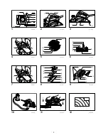
Page 2: ...1 2 1 011864 1 2 2 011865 1 2 3 3 011866 1 2 4 011867 1 2 3 4 5 5 002555 1 2 3 4 5 6 7 8 9 6 002556 1 2 7 011867 1 2 3 4 5 6 7 8 9 10 8 011927 1 2 3 4 5 6 7 9 011928 10 011868 1 2 11 011869 12 002580...

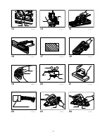
Page 3: ...3 1 2 13 011870 1 2 14 011871 15 011872 16 010183 17 003634 18 011873 1 19 002588 1 2 3 4 5 20 002589 21 002590 1 22 001145 1 2 23 011874 1 2 24 011875...

Page 4: ...0 Overall length 285 mm Net weight 2 7 kg Safety class II Due to our continuing programme of research and development the specifications herein are subject to change without notice Specifications may...

Page 5: ...the power tool live and could give the operator an electric shock 3 Use clamps or another practical way to secure and support the workpiece to a stable platform Holding the work by hand or against you...

Page 6: ...llation bolt can be dangerous Always check to see they are tightened securely Handle the blades very carefully Use gloves or rags to protect your fingers or hands when removing or installing the blade...

Page 7: ...he other blade For the correct planer blade setting Your planing surface will end up rough and uneven unless the blade is set properly and securely The blade must be mounted so that the cutting edge i...

Page 8: ...s shown in the figure align the V groove in the front base with the edge of the workpiece and plane it MAINTENANCE CAUTION Always be sure that the tool is switched off and unplugged before attempting...

Page 9: ...6 8 6 9 7 1 7 2 8 1 8 2 8 3 8 4 8 5 8 6 8 7 8 8 8 9 8 10 9 1 9 2 9 3 9 4 9 5 9 6 9 7 11 1 11 2 13 1 13 2 14 1 14 2 19 1 20 1 20 2 20 3 20 4 D 20 5 22 1 23 1 23 2 24 1 24 2 MT191 82 2 9 1 16000 285 2 7...

Page 10: ...Corporation Makita MT191 2006 42 EC EN60745 Makita International Europe Ltd Michigan Drive Tongwell Milton Keynes Bucks MK15 8JD 23 11 2010 000230 Tomoyasu Kato Makita Corporation 3 11 8 Sumiyoshi cho...

Page 11: ...11 11 12 13 14 15 16 17 Makita 18 Fig 1 Fig 2 Fig 3...

Page 12: ...12 Makita Fig 4 Fig 5 Fig 6 Fig 7 1 Fig 8 2 3 4 5 Fig 9 6 7 8 9 10 1 9...

Page 13: ...13 A B B A B A EN0004 1 Fig 10 Makita Fig 11 Fig 12 Fig 13 Fig 14 Fig 15 9 Fig 16...

Page 14: ...14 Fig 17 Fig 18 V Fig 19 Fig 20 D Fig 21 2 3 Fig 22 Fig 23 Fig 24...

Page 15: ...chwyt do ostrzenia 20 1 Nakr tka motylkowa 20 2 Ostrze A 20 3 Ostrze B 20 4 Bok D 20 5 Bok C 22 1 Znak ograniczenia 23 1 Os ona przeciwwi rowa lub dysza 23 2 rubokr t 24 1 Pokrywka uchwytu szczotki 24...

Page 16: ...n Drive Tongwell Milton Keynes Bucks MK15 8JD Anglia 23 11 2010 000230 Tomoyasu Kato Dyrektor Makita Corporation 3 11 8 Sumiyoshi cho Anjo Aichi 446 8502 JAPONIA GEA010 1 Og lne zasady bezpiecze stwa...

Page 17: ...nia dzia ania elektronarz dzia nale y upewni si czy jest ono wy czone i nie pod czone do sieci Dostosowywanie g boko ci ci cia Rys 1 G boko ci cia mo na atwo regulowa obracaj c pokr t o znajduj ce si...

Page 18: ...dur dla drugiego no a W przypadku narz dzia z ma ymi no ami dwustronnymi Rys 7 1 Je li narz dzie by o u ywane usu zamontowany n dok adnie wyczy powierzchnie wa ka i os ony Aby wymontowa no e z wa ka n...

Page 19: ...s 11 Najpierw oprzyj przedni podstaw narz dzia na powierzchni obrabianego materia u tak aby nie styka y si z ni no e W cz urz dzenie i zaczekaj a no e osi gn pe n pr dko Nast pnie przesu narz dzie pow...

Page 20: ...z t dodatkowy Rys 20 Nale y najpierw poluzowa dwie nakr tki motylkowe uchwytu i wsun no e A i B tak by dotyka y bok w C i D Nast pnie nale y nakr tki dokr ci Rys 21 Przed ostrzeniem ose k nale y przez...

Page 21: ...SPECIFICA II Model MT191 L ime de rindeluire 82 mm Ad ncime de rindeluire 2 mm Ad ncime de f l uire 9 mm Tura ia n gol min 1 16 000 Lungime total 285 mm Greutate net 2 7 kg Clasa de siguran II Datorit...

Page 22: ...v 2 ine i ma ina electric doar de suprafe ele de prindere izolate deoarece cu itul poate intra n contact cu propriul fir T ierea unui fir sub tensiune va pune sub tensiune i componentele metalice expu...

Page 23: ...deblocare Comutatorul se poate rupe Picior Fig 3 Dup o opera ie de a chiere ridica i partea posterioar a ma inii i piciorul este proiectat sub nivelul p r ii din spate a t lpii Acesta previne deterior...

Page 24: ...ba i cele trei uruburi astfel nc t s existe un spa iu ntre tambur i placa de reglare pentru a putea introduce mini cu itul de rindea n pozi ie Cu itul va fi pozi ionat de c tre proeminen ele pentru fi...

Page 25: ...ei buc i de lemn suplimentare n opritor sunt prev zute orificii convenabile n acest scop precum i pentru ata area unui ghidaj de extensie accesoriu op ional NOT Forma riglei de ghidare difer de la o a...

Page 26: ...nf nger oder Stutzen 23 2 Schraubendreher 24 1 Kohlenhalterdeckel 24 2 Schraubendreher TECHNISCHE DATEN Modell MT191 Hobelbreite 82 mm Hobeltiefe 2 mm Falztiefe 9 mm Leerlaufdrehzahl min 1 16 000 Gesa...

Page 27: ...sorgf ltig durch Werden die Warnungen und Anweisungen ignoriert besteht die Gefahr eines Stromschlags Brands und oder schweren Verletzungen Bewahren Sie alle Warnhinweise und Anweisungen zur sp teren...

Page 28: ...Stecker aus der Dose gezogen ist Einstellen der Schnitttiefe Abb 1 Die Schnitttiefe kann einfach durch Drehen des Knopfes an der Vorderseite des Werkzeugs eingestellt werden bis der Zeiger auf der gew...

Page 29: ...s vorhandene Messer Falls das Werkzeug im Betrieb war reinigen Sie die Oberfl chen der Hobelwelle sowie die Druckplatte sorgf ltig L sen Sie zur Demontage der Messer an der Hobelwelle die drei Befesti...

Page 30: ...uerst den vordere Werkzeuggleitschuh flach auf das Werkst ck ohne dass die Hobelmesser irgendwelchen Kontakt haben Schalten Sie das Werkzeug ein und warten Sie bis die Messer ihre volle Drehzahl errei...

Page 31: ...derzubeh r Kerben und schleifen Sie eine feine Kante Abb 20 L sen Sie zun chst die beiden Fl gelmuttern an der Haltevorrichtung und setzen Sie die Messer A und B so ein dass sie die Seiten C und D ber...

Page 32: ...ss g 82 mm Gyalul si m lys g 2 mm Haj padl z si m lys g 9 mm resj rati sebes g min 1 16 000 Teljes hossz 285 mm Tiszta t meg 2 7 kg Biztons gi oszt ly II Folyamatos kutat s fejleszt programunk eredm n...

Page 33: ...thatatlans g hoz s komoly s r l sekhez vezethet 2 Kiz r lag a szigetelt markol si fel letein l fogva tartsa az elektromos szersz mot mivel fenn ll a vesz lye hogy a v g k s a saj t vezet kbe tk zik A...

Page 34: ...t a le ll t shoz VIGY ZAT Ne h zza t lzott er vel a kiold kapcsol t ha nem nyomta be a kireteszel gombot Ez a kapcsol t r s t okozhatja Talp Fig 3 Egy v g si m veletet k vet en emelje fel a szersz m h...

Page 35: ...dobfedelet a be ll t lemez r gz t lemez f l s csavarja be a h rom csavart gy hogy a dob s a r gz t lemez k z tt maradjon h zag a mini gyaluk sek helyrecs sztat s hoz A k st a r gz t lemez gyaluk start...

Page 36: ...len lehet A maxim lis haj padl z si sszeereszt si m lys g 9 mm Fig 16 Lehet hogy meg szeretn majd hosszabb tani a vezet hossz t egy fadarab hozz illeszt s vel Erre a c lra a vezet furatokkal van ell t...

Page 37: ...kef ket tegye be az jakat s helyezze vissza a kefetart sapk kat A term k BIZTONS G NAK s MEGB ZHAT S G NAK fenntart s hoz a jav t sokat b rmilyen egy b karbantart st vagy beszab lyoz st a Makita Autor...

Page 38: ...20 3 epe B 20 4 Strana D 20 5 Strana C 22 1 Medzn zna ka 23 1 Kryt na triesky alebo tryska 23 2 Skrutkova 24 1 Veko dr iaka uhl ka 24 2 Skrutkova TECHNICK DAJE Model MT191 rka hob ovania 82 mm H bka h...

Page 39: ...ov a in trukci m e ma za n sledok raz elektrick m pr dom po iar alebo v ne zranenie V etky pokyny a in trukcie si odlo te pre pr pad potreby v bud cnosti GEB010 4 BEZPE NOSTN V STRAHY PRE HOB OVA KU 1...

Page 40: ...idlom Aby nedoch dzalo n hodn mu potiahnutiu sp acieho sp na a nach dza sa tu odomykacie tla idlo Ak chcete spusti n stroj stla te odomykacie tla ilo a potiahnite sp ac sp na Zastav te ho uvo nen m s...

Page 41: ...ky zasu te do ryhy na valci Fig 9 6 Kryt valca nastavte nad nastavovaciu dosku a priskrutkujte ho tromi skrutkami tak aby medzi valcom a nastavovacou doskou existovala medzera na posunutie mini hob ov...

Page 42: ...the fence by attaching an extra piece of wood Pre tento el ako aj pre pripevnenie vodidla pred enia volite n pr slu enstvo sa v ochrannom zariaden nach dzaj vhodn otvory POZN MKA Tvar vodiaceho prav...

Page 43: ...ICK DAJE Model MT191 ka hoblov n 82 mm Hloubka hoblov n 2 mm Hloubka polodr kov n 9 mm Ot ky napr zdno min 1 16 000 Celkov d lka 285 mm Hmotnost netto 2 7 kg T da bezpe nosti II Vzhledem k neust l mu...

Page 44: ...2 Elektrick n ad dr te pouze za izolovan sti dr adel nebo ezn n stroj m e narazit na vlastn nap jec kabel Zasa en m vodi e pod nap t m se m e proud p en st do nechr n n ch kovov ch st n ad a obsluha...

Page 45: ...ak koliv pr ce v dy se p edt m p esv d te e je vypnut a vyta en ze z suvky Demont a instalace hoblovac ch no POZOR P i instalaci no na n stroj je nutno pevn dot hnout instala n rouby no Uvoln n instal...

Page 46: ...dota en t roub 10 Opakujte kroky 1 9 u druh ho no e Spr vn nastaven hoblovac ho no e Nebude li spr vn a bezpe n nastaven n bude hoblovan povrch hrub a nerovn N je nutno namontovat tak aby byla ezn hra...

Page 47: ...st standardn ho p slu enstv kosov n Fig 17 Fig 18 Chcete li prov st kosovac ez jak je ilustrov no na obr zku vyrovnejte dr ku V na p edn z kladn s okrajem zpracov van ho d lu a prove te innost DR BA P...

Page 48: ...48 Makita Corporation Anjo Aichi Japan www makita com 885032 979...

Reviews: