background image

8

Removing or installing planer blades

CAUTION:

• Tighten the blade installation bolts carefully when 

attaching the blades to the tool. A loose installation bolt 
can be dangerous. Always check to see they are 
tightened securely.

• Handle the blades very carefully. Use gloves or rags to 

protect your fingers or hands when removing or 
installing the blades.

• Use only the Makita wrench provided to remove or 

install the blades. Failure to do so may result in 
overtightening or insufficient tightening of the 
installation bolts. This could cause an injury.

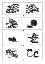
For tools with conventional planer blades (Fig. 3, 
Fig. 4 & Fig. 5)

To remove the blades on the drum, unscrew the three 
installation bolts with the socket wrench. The drum plate 
comes off together with the blades.
To install the blades, first clean out all chips or foreign 
matter adhering to the drum or blades. Use blades of the 
same dimensions and weight, or drum oscillation/vibration 
will result, causing poor planing action and, eventually, 
tool breakdown.
Place the blade on the gauge base so that the blade edge 
is perfectly flush with the inside edge of the gauge plate. 
Place the adjusting plate on the blade, then simply press 
in the heel of the adjusting plate flush with the back side of 
the gauge base and tighten two screws on the adjusting 
plate. Now slip the heel of the adjusting plate into the 
drum groove, then fit the drum cover on it. Tighten the 
three installation bolts evenly and alternately with the 
socket wrench.

For tool with mini planer blades (Fig. 3, Fig. 6 & Fig. 7)

1. Remove the existing blade, if the tool has been in use, 

carefully clean the drum surfaces and the drum cover. 
To remove the blades on the drum, unscrew the three 
installation bolts with the socket wrench. The drum 
cover comes off together with the blades.

2. To install the blades, loosely attach the adjusting plate 

to the set plate with the pan head screws and set the 
mini planer blade on the gauge base so that the 
cutting edge of the blade is perfectly flush with the 
inside flank of the gauge plate.

3. Set the adjusting plate/set plate on the gauge base so 

that the planer blade locating lugs on the set plate rest 
in the mini planer blade groove, then press in the heel 
of the adjusting plate flush with the back side of the 
gauge base and tighten the pan head screws.

4. It is important that the blade sits flush with the inside 

flank of the gauge plate, the planer blade locating lugs 
sit in the blade groove and the heel of the adjusting 
plate is flush with the back side of the gauge base. 
Check this alignment carefully to ensure uniform 
cutting.

5. Slip the heel of the adjusting plate into the groove of 

the drum.

6. Set the drum cover over the adjusting plate/set plate 

and screw in the three hex flange head bolts so that a 
gap exists between the drum and the set plate to slide 
the mini planer blade into position. The blade will be 
positioned by the planer blade locating lugs on the set 
plate.

7. The blade's lengthwise adjustment will need to be 

manually positioned so that the blade ends are clear 
and equidistant from the housing on one side and the 
metal bracket on the other.

8. Tighten the three hex flange head bolts (with the 

socket wrench provided) and rotate the drum to check 
clearances between the blade ends and the tool body.

9. Check the three hex flange head bolts for final 

tightness.

10. Repeat procedures 1 - 9 for other blade.

Summary of Contents for MT111

Page 1: ...GB Power Planer Instruction manual ID Mesin Serut Listrik Petunjuk penggunaan M y B o C m Tay Ho t ng B ng ng C i n VI T i li u h ng d n TH MT111...

Page 2: ...2 1 013190 2 013191 3 013192 4 013185 5 002556 6 013186 7 013312 8 013194 1 2 3 5 4 6 7 7 8 9 10 11 12 13 9 11 14 15 16 17 18 14 11 19 17 20 21 22 18 16 23 8 23 21 11 7 10 14 24 25...

Page 3: ...3 9 013196 10 002580 11 013314 12 013313 13 013198 14 003634 15 013203 16 002588 26 27 3 28 13 29 14 30 31 32...

Page 4: ...4 17 004952 18 004953 33 34 35 37 36...

Page 5: ...ectric shock fire and or serious injury Save all warnings and instructions for future reference The term power tool in the warnings refers to your mains operated corded power tool or battery operated...

Page 6: ...ting Ensure the switch is in the off position before connecting to power source and or battery pack picking up or carrying the tool Carrying power tools with your finger on the switch or energising po...

Page 7: ...8 Hold the tool firmly with both hands 9 Keep hands away from rotating parts 10 Before using the tool on an actual workpiece let it run for a while Watch for vibration or wobbling that could indicate...

Page 8: ...ly clean the drum surfaces and the drum cover To remove the blades on the drum unscrew the three installation bolts with the socket wrench The drum cover comes off together with the blades 2 To instal...

Page 9: ...The speed and depth of cut determine the kind of finish The power planer keeps cutting at a speed that will not result in jamming by chips For rough cutting the depth of cut can be increased while fo...

Page 10: ...y other maintenance or adjustment should be performed by Makita Authorized or Factory Service Centers always using Makita replacement parts Sharpening the planer blades only for tool with conventional...

Page 11: ...k yang tercantum di bawah ini dapat menyebabkan sengatan listrik kebakaran dan atau cedera serius Simpanlah semua peringatan dan petunjuk untuk acuan di masa depan Istilah mesin listrik dalam semua pe...

Page 12: ...aspadaan perhatikan pekerjaan Anda dan gunakan akal sehat bila menggunakan mesin listrik Jangan menggunakan mesin listrik saat Anda lelah atau di bawah pengaruh obat bius alkohol atau obat Sekejap saj...

Page 13: ...nya suku cadang pengganti yang serupa Hal ini akan menjamin terjaganya keamanan mesin listrik 2 Patuhi petunjuk pelumasan dan penggantian aksesori GEB167 1 Peringatan Keselamatan Mesin Serut 1 Tunggu...

Page 14: ...teromol lepas ketiga baut pengikat dengan menggunakan kunci sok Pelat teromol akan terlepas bersama mata pisaunya Untuk memasang mata pisau pertama tama bersihkan semua sepihan kayu atau benda asing y...

Page 15: ...ara berkala Gunakan udara terkompresi untuk membersihkan nosel yang tersumbat PENGGUNAAN PERINGATAN Untuk mengurangi risiko cedera pada seseorang jangan operasikan dengan nosel atau tutup serpihan kay...

Page 16: ...panjang penahan tepi dengan memasang potongan kayu tambahan Lubang lubang yang sesuai untuk tujuan ini tersedia pada penahan tepi Memotong miring Gb 14 Gb 15 Untuk membuat potongan miring seperti ditu...

Page 17: ...m y n y Vi c kh ng tu n theo c c h ng d n c li t k d i y c th d n n i n gi t h a ho n v ho c th ng t ch nghi m tr ng L u gi t t c c nh b o v h ng d n tham kh o sau n y Thu t ng d ng c m y trong c c c...

Page 18: ...u c Ch m t kho nh kh c kh ng t p trung khi ang v n h nh d ng c m y c ng c th d n n th ng t ch c nh n nghi m tr ng 2 S d ng thi t b b o h c nh n Lu n eo thi t b b o v m t C c thi t b b o h nh m t n ch...

Page 19: ...o i b h c a d ng c m y c i n v l m cho ng i v n h nh b i n gi t 3 S d ng c c ch t k p ho c nh ng c ch th c t kh c gi ch t v l y ph i gia c ng tr n b c v ng ch c N m gi ph i gia c ng b ng tay ho c t a...

Page 20: ...p trong c a t m c t t m i u ch nh tr n l i b o sau ch c n nh n ph n g y c a t m i u ch nh cho n m ngang v i m t sau c a c v v n ch t hai v t tr n t m i u ch nh B y gi m i tr t ph n g y c a t m i u ch...

Page 21: ...n tr c d ng c v o l c b t u ng b o v l n ph n sau d ng c khi k t th c ng b o S d b o h n n u b n t nghi ng v t gia c ng theo ki u c nh sao cho b n c th b o theo h ng d c xu ng T c v chi u s u c t s q...

Page 22: ...a ch t t ng t C th x y ra hi n t ng m t m u bi n d ng ho c n t v m b o AN TO N v TIN C Y c a s n ph m vi c s a ch a vi c ki m tra v thay th ch i c c bon ho c b t c thao t c b o tr i u ch nh n o u ph i...

Page 23: ...23 EPTA 01 2014 END201 7 ENE001 1 ENF002 2 1 2 3 4 5 6 7 8 9 10 11 12 13 14 15 16 17 18 19 20 21 22 23 24 25 26 27 28 29 30 31 V 32 33 34 A 35 B 36 D 37 C MT111 82 3 20 18 000 390 4 5 4 6 II...

Page 24: ...24 GEA012 2 1 2 3 1 2 3 4 5 6 RCD RCD 7 RCD 30 mA 8 EMF 9 10 1 2 3 4 5 6 7...

Page 25: ...25 8 9 ANSI Z87 1 EN 166 AS NZS 1336 1 2 3 4 5 6 7 8 9 1 2 GEB167 1 1 2 3 4 5 6...

Page 26: ...26 7 8 9 10 11 12 13 14 15 16 17 Makita 18 1 2 OFF Makita 3 4 5...

Page 27: ...27 3 6 7 1 2 3 4 5 6 7 8 9 10 1 9 A B EN0004 1 A B B A B A...

Page 28: ...28 8 1 2 3 9 10 0 3 0 6 11 12 13 20 14 15 V Makita Makita 16 A B C D 17 2 3 18...

Page 29: ...29...

Page 30: ...30...

Page 31: ...31...

Page 32: ...885156B375 TRD Makita Corporation 3 11 8 Sumiyoshi cho Anjo Aichi 446 8502 Japan www makita com...

Reviews: