P 12/ 19
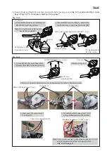
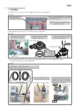
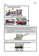
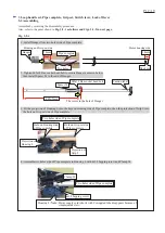
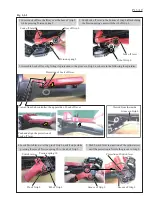
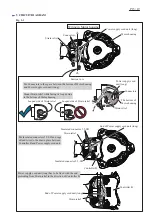
Fig. 3-2-1
1. Install Hanger from two holes side of Pipe complete.
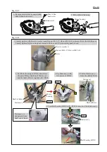
Assemble by reversing the disassembly procedure.
Also, refer to the point shown in
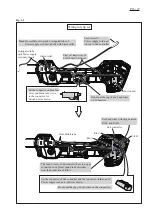
Fig. 3-2-1 as follows and Figs. 3-2-2 in next page.
2. Tighten M5x18 Hex socket head bolt to secure Hanger as drawn below,
then install Spacer 24 to the end of Hanger.
3. Fit the projection of Housing L into the hole on Housing side of Pipe complete, then the projection of Grip L into
the hole on Grip set side of Pipe complete.
4. Assemble two holes side of Pipe complete to Housing L with 4x18 Tapping screw and Clamp 24.
Housing and Grip set side
Motor housing side
3 Loop handle set, Pipe complete, Grip set, Switch lever, Lock off lever
3-2 Assembling
Pipe complete
Hanger
Spacer 24
Caution label
34mm
14mm
Two holes
One hole
482±3mm
The center in the hole of Hanger
M5x18 Hex socket head bolt
Hole on Housing side
of Pipe complete
Hole on Grip set side
of Pipe complete
Projection of
Housing L
Two holes side of Pipe complete
Two holes side of Pipe complete
Projection of
Grip L
4x18 Tapping screw
Clamp 24
Housing L/
Note
: Power supply cord (short) with Corrugated tube disappears because of
simple inside view.
Summary of Contents for XRU09
Page 1: ...REPAIR MANUAL XRU09...


