

P 3 / 7
R
epair
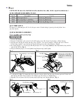
[3] -1. Spindle and Gear Section (cont.)
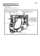
Fig. 6
Fig. 5
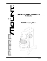
ASSEMBLING
Ball Bearing 607LLB
(for Gear Complete 12-41)
Gear Housing
1) Put Ball bearing 607LLB in place into the bearing box portion
of Gear housing. (Fig. 5)
2) Press-fit Spindle into Ball bearing 6202LLB using arbor press.
Then assemble the Spindle to Gear housing.
3) Assemble Bearing retainer 22-36 to Gear housing fixed in vise.
(Fig. 2)
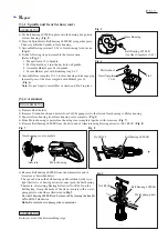
4) Do the following steps to assemble the Gear section.
(Refer to Fig. 3.)
1. Mount Sleeve 15 to Spindle.
2. Put Woodruff key 4 into the key hole on Spindle.
3. Assemble Helical gear 34 to Spindle.
4. Secure Helical gear with Retaining ring S-15.
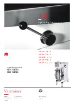
5) Assemble Gear complete 12-41 to Gear housing while engaging
the small gear of the Gear complete with Helical gear 34.
(Fig. 6)
Note: Do not forget to install Flat washer 6 and Pin 3 in place.
Pin 3
Flat washer 6
Gear Complete
12-41
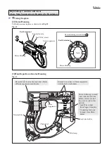
1) Remove Shaft holder.
2) Remove Carbon brush, and unscrew four 5x40 Tapping screws that fasten Gear housing to Motor housing.
3) Separate Gear housing from Gear housing cover complete. (Fig. 1)
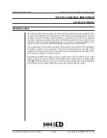
4) From Motor housing, separate Gear housing cover complete together with Armature. (Fig. 7)
5) Remove Ball bearing 608LLB from the drive-end of Armature using Bearing extractor (No.1R269). (Fig. 8)
[3] -2. Armature
DISASSEMBLING
Fig. 7
Fig. 8
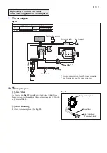
Fig. 9
ASSEMBLING
Do the reverse of the disassembling steps.
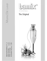
6) Remove Ball bearing 608LLB from the commutator end of
Armature as described below:
The space between the ball bearing and Insulation washer is so
tight that claws of bearing extractor cannot grab the ball bearing.
Therefore, after setting Bearing Extractor (No.1R269) on the
ball bearing, clamp the backs of the claws securely with a water
pump pliers or the like as illustrated in Fig. 9
.
Now ball bearing 608LLB can be removed by turning the handle
of No.1R269 clockwise.
Note: Be careful not to damage the commutator.
Gear housing cover complete
Armature
No.1R269
Ball bearing 608LLB
Ball Bearing 608LLB
No.1R269
Water pump pliers
Motor housing