19 ENGLISH
ASSEMBLY
CAUTION:
Always be sure that all the battery
cartridges are removed before carrying out any
work on the machine.
Failure to remove all the bat
-
tery cartridges may result in serious personal injury
from accidental start-up.
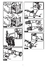
Assembling blower pipes
1.
Loosen the clamp screw.
►
Fig.2:
1.
Clamp screw
2.
Install the control handle to the swivel pipe and
tighten the clamp screw.
►
Fig.3:
1.
Control handle
2.
Swivel pipe
3.
Clamp
screw
NOTICE:
Be careful not to twist the cable of the
control handle when attaching the control handle
to the swivel pipe.
3.
Loosen the screw on the hose clamp, and then
attach the hose clamp to the end nozzle. Align the
grooves on the end nozzle with the protrusions on the
swivel pipe, then attach the end nozzle to the swivel
pipe, and then tighten the screw on the hose clamp.
►
Fig.4:
1.
End nozzle
2.
Hose clamp
3.
Swivel pipe
4.
Groove
5.
Protrusion
6.
Screw
4.
Loosen the screw on the hose clamp, then attach
the nozzle lever to the hose clamp, and then attach the
hose clamp to the flexible pipe. Attach the swivel pipe to
the flexible pipe, and then tighten the screw on the hose
clamp.
►
Fig.5:
1.
Swivel pipe
2.
Nozzle lever
3.
Hose clamp
4.
Flexible pipe
5.
Screw
5.
Loosen the screw on the hose clamp, and then
attach the hose clamp to the flexible pipe. Attach the
flexible pipe to the elbow, and then tighten the screw on
the hose clamp.
►
Fig.6:
1.
Flexible pipe
2.
Hose clamp
3.
Elbow
NOTICE:
Make sure that the screw on the hose
clamp is not facing outward as shown in the
figure.
►
Fig.7:
1.
Screw
6.
Clamp the control cable to the cable holders.
►
Fig.8:
1.
Cable holder
2.
Control cable
NOTICE:
Make sure that the control cable is
securely fixed to the cable holder.
Adjusting the belt and shoulder
harness
1.
Put on the machine, then lock the buckle of the
waist belt, and then adjust the length of the waist belt.
►
Fig.9:
1.
Buckle
2.
Adjust the length of the shoulder harness.
►
Fig.10:
1.
Shoulder harness
Adjusting the control lever position
Loosen the clamp screw. Move the control handle along
the swivel pipe to the most comfortable position, and
then tighten the clamp screw.
►
Fig.11:
1.
Control handle
2.
Swivel pipe
3.
Clamp
screw
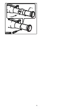
Attaching the diffusion cover
You can diffuse the mist by attaching the diffusion cover
to the end nozzle as shown in the figure.
►
Fig.12:
1.
Diffusion cover
Attaching the deflector
Optional accessory
You can discharge the mist upward or downward by
attaching the deflector to the end nozzle as shown in
the figure.
►
Fig.13:
1.
Deflector
FUNCTIONAL
DESCRIPTION
CAUTION:
Always be sure that the machine
is switched off and all the battery cartridges are
removed before adjusting or checking function on
the machine.
Installing or removing battery
cartridge
CAUTION:
Always switch off the machine
before installing or removing of the battery
cartridge.
CAUTION:
Hold the machine and the battery
cartridge firmly when installing or removing bat
-
tery cartridge.
Failure to hold the machine and the
battery cartridge firmly may cause them to slip off
your hands and result in damage to the machine and
battery cartridge and a personal injury.
CAUTION:
Make sure that you lock the battery
cover before use.
Otherwise, mud, dirt, or water may
cause damage to the product or the battery cartridge.
CAUTION:
Always install the battery cartridge
fully until the red indicator cannot be seen.
If not,
it may accidentally fall out of the machine, causing
injury to you or someone around you.
CAUTION:
Do not install the battery cartridge
forcibly.
If the cartridge does not slide in easily, it is
not being inserted correctly.
CAUTION:
Hold the battery cover firmly when
installing or removing the battery cartridge.
Summary of Contents for PM001G
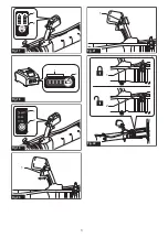
Page 2: ...2 0 30 30 Fig 1 1 Fig 2 1 2 3 Fig 3 6 1 2 3 4 5 Fig 4 2 1 4 3 5 Fig 5 ...
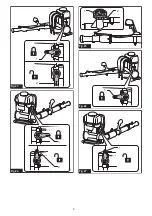
Page 3: ...3 3 2 1 Fig 6 1 Fig 7 1 2 Fig 8 1 Fig 9 1 Fig 10 ...
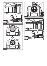
Page 4: ...4 1 2 3 Fig 11 1 Fig 12 1 Fig 13 1 2 Fig 14 1 Fig 15 1 Fig 16 ...
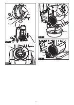
Page 5: ...5 1 2 Fig 17 1 2 Fig 18 1 2 Fig 19 1 Fig 20 1 Fig 21 1 2 Fig 22 ...
Page 6: ...6 1 2 Fig 23 1 2 Fig 24 2 1 Fig 25 1 Fig 26 1 Fig 27 ...
Page 7: ...7 1 Fig 28 1 2 Fig 29 Fig 30 1 Fig 31 ...
Page 8: ...8 1 Fig 32 1 Fig 33 1 2 Fig 34 1 Fig 35 ...
Page 9: ...9 2 1 Fig 36 1 Fig 37 1 2 Fig 38 1 2 Fig 39 1 2 3 Fig 40 1 2 Fig 41 ...
Page 10: ...10 1 2 Fig 42 ...
Page 99: ...99 ...

