background image

P 5/ 12

R

epair

[3] DISASSEMBLY/ASSEMBLY

[3] -2. Helical Gear 39, Ball Bearing 6002LLB (cont.)

DISASSEMBLING

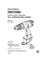
(3) Disassemble the removed Spindle section as drawn in 

Fig. 4

.

ASSEMBLING

(1) Assemble Compression spring 16 and Ball bearing 6002LLB to Spindle. And secure them with Ring spring 13.

      (Refer to the  

lower two

 illustrations in 

Fig. 4

.)

Note

: Apply a little amount of 

Makita grease N. No.2

 to Drum portion of Spindle and in the inner ring the bearing.

          (Refer to 

[2] LUBRICATION

.)

(2) Assemble Helical gear 39 to Spindle as drawn in 

Fig. 5

.

Fig. 4

3. Ball bearing 6002LLB and Compression spring 16 are secured to Spindle with Ring spring 13.  

    Remove Ring spring 13 with 1R004. Now, Ball bearing 6002LLB and Compression spring 16 

    are removed from Spindle.

1. Put the removed Spindle section onto

   1R165 to support Helical gear 39.

2. Remove Helical gear 39 by pressing the Spindle end

    with Arbor press.

Spindle

1R029

1R165

1R165

Helical gear 39

Spindle

Helical gear 39

Spindle end

Ring spring 13

1R004

Ball bearing 6002LLB

Ball bearing

6002LLB

Cam portion

1. Set the Spindle section to 1R139.

2. Apply 1R029 to Helical gear 39, and press 1R029 with Arbor press

    to assemble the gear to the Spindle section.


Note

: Face the cam portion of Helical gear 39 to the opposite side

              to


Ball bearing 6002LLB

Compression spring 16

Fig. 5

Summary of Contents for MT80A

Page 1: ...e Hz Input Output Max Output W Current A Dimensions mm Width W Height H Length L 262 10 3 8 MT80B 254 10 MT80A 196 7 3 4 70 2 3 4 Chuck capacity mm Chuck type Reverse switch Impacts per min min ˉ ipm Capacities mm Steel Concrete Wood Protection against electric shock Power supply cord m ft Weight according to EPTA Procedure 01 2003 kg lbs 0 2 900 Model No MT80B 0 43 500 Keyed 1 5 13 1 16 1 2 16 5 ...

Page 2: ...m Drill chuck for 10 mm Drill chuck 2 LUBRICATION Apply Makita grease N No 2 to the following portions designated with the black triangle to protect parts and product from unusual abrasion Fig 1 Item No Description Spindle a little a little 3 0g 1 7g a little a little a Drum portion for smooth hammering in the inner ring of Ball bearing 6002LLB b Spindle end where 10 Steel ball 5 contacts Steel ba...

Page 3: ...9 2 Attach 1R224 to 1R223 and set them to 1R298 3 Turn 1R223 counter clockwise to remove 13mm Drill chuck from the machine 1R139 1R298 1R224 1R223 Fig 2A Fig 2B 3 1B 10mm Drill Chuck of model MT80A 1R139 1R224 1R231 Bit adapter 1R223 1 Fix 1R139 firmly with vise Then attach 1R231 and Bit adapter to 10mm Drill chuck and then fix the machine to 1R139 by fitting the flat portion of Spindle to the gro...

Page 4: ...n Fig 2A or Fig 2B 2 Remove Spindle section from the machine as illustrated in Fig 3 Fig 3 3 Shift Change lever to Hammer drill mode 1 Shift Change lever to Drill mode 2 Remove Housing R by loosening seven 4x18 Tapping screws 4 Hold Spindle and Change lever by hand then Lift up Spindle and Change lever while turning them counter clockwise viewing them from Drill chuck side 5 Pull off the Spindle s...

Page 5: ...LB and Compression spring 16 are secured to Spindle with Ring spring 13 Remove Ring spring 13 with 1R004 Now Ball bearing 6002LLB and Compression spring 16 are removed from Spindle 1 Put the removed Spindle section onto 1R165 to support Helical gear 39 2 Remove Helical gear 39 by pressing the Spindle end with Arbor press Spindle 1R029 1R165 1R165 Helical gear 39 Spindle Helical gear 39 Spindle end...

Page 6: ...Change lever Spindle section Housing L 1 Shift Change lever to Drill mode and separate Housing R from Housing L by unscrewing seven 4x18 Tapping screws See the upper two illustrations in Fig 3 2 Shift Change lever back to Hammer drill mode and remove the Spindle section from Cam holder complete See the lower illustrations in Fig 3 3 Disassemble Cam holder complete as drawn in Fig 7 Cam holder comp...

Page 7: ... 1R258 1R258 Put Cam holder complete onto 1R258 and set 2 pcs of 1R278 to the holes of Cam holder complete And then press 2 pcs of 1R278 with Arbor press to disassemble Cam complete from Cam holder Cam complete Cam holder 1 Set Cam complete to Cam holder while aligning the notch of Cam complete to the small square mark on Cam holder 2 Put Cam holder with Cam complete onto 2 pcs of 1R258 And apply ...

Page 8: ...tting it to the groove in Cam holder complete Steel ball 5 2 Apply a little amount of Makita grease N No 2 to Change lever at the portion designated with black triangle And mount Steel ball 5 to Change lever Projection Projection Groove Change lever Cam side of Cam holder complete Change lever 3 Assemble Change lever to Cam holder complete as drawn below Note Fit Projection of the lever to the gro...

Page 9: ...Black Red Orange Purple Areas where suppression of radio interference is required Fig D 1 Brush holder A Top Top view Left Left side view Brush holder B Choke coil purple Choke coil orange Field Power supply cord Switch Switch Noise suppressor Blue lead wire is used for some countries Brown lead wire is used for some countries ...

Page 10: ...ng the window of Brush holder to Housing L side put it in the position of Change lever side While facing the window of Brush holder to Housing R side put it in the position of Switch side Power supply cord Noise suppressor Put Choke coil purple in the position shown below Put Choke coil orange in the position shown in the right Fix Field lead wires black with this Lead wire holder Put Field lead w...

Page 11: ...dex of lead wires sheath Black Red Orange Purple Areas where suppression of radio interference is not required Fig D 1A Brush holder A Top Top view Left Left side view Brush holder B Field Power supply cord Switch Switch Blue lead wire is used for some countries Brown lead wire is used for some countries ...

Page 12: ...side Switch Change lever side Window of Brush holder Brush holder Brush holder While facing the window of Brush holder to Housing L side put it in the position of Change lever side While facing the window of Brush holder to Housing R side put it in the position of Switch side Power supply cord Fix Field lead wires black with this Lead wire holder Put Field lead wires and Power supply cord brown or...

Reviews: