P 4 / 5
R
epair
[1] DISASSEMBLY/ASSEMBLY
[1] -3. Varistor and Fuse
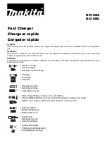
Fig. 7
Varistor
Varistor
Pt. No.647306-1 for High Voltage H= 22mm
Pt. No.647321-5 for Low voltage H= 20mm
Distinction of high voltage from low voltage
2) Replacing Varistor/Fuse
The varistors are different, and installs depending on the voltage. The distinction can be made as illustrated in Fig. 6.
Varistor/fuse is soldered on the charging circuit. Remove a broken varistor/fuse with soldering iron.
And solder brand-new one with soldering iron. (Fig. 7)
1) Types of Breakage
Sign of varistor breakage
a) Cracks in the surface of varistor
b) Black discolored surface of varistor
1. If fuse is broken, varistor is usually broken by showing the sign of breakage mentioned below.
In this case, replace fuse and varistor at the same time.
2. Only
varistor can be damaged if charger is plugged in a power source at double the rated voltage.
In this case, replace varistor solely.
3. If fuse is broken while varistor is not broken, charging circuit can be broken.
In this case, replace charging circuit complete.
H
Fig. 6
Fuse
Charging
Circuit