P 2 / 5
R
epair
[1] DISASSEMBLY/ASSEMBLY
[1] -1. Terminal Unit
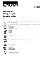
Fig. 1
Fig. 2
Fig. 3
CAUTION: Disconnect the charger from the power source for safety
before repair/ maintenance !
DISASSEMBLING
Cap 13: 4 pcs.
Tapping
Screw 4x20: 4 pcs.
Charger Case
Cover
Charger Case
Cover
Charger Case
Complete
1. Remove four caps 13 and four 4x20 tapping screws. Consequently, charger case complete can be separated
from charger case cover. (Fig. 1)
< Note >
When removing charger case complete from charger case cover, be sure to put the product on the work bench, with
charger case complete faced to the upper side.
2. Loosen band with which bundles lead wires of terminal unit and that of cirocco fan. Disconnect connector 1 and
connector 2, and remove terminal unit from charger case cover. (Fig. 2)
Compression
Spring 4
Terminal Unit
Band
Connector 1
Band
Connector 2
ASSEMBLING
1. Insert compression spring 4 over the boss for accepting
the compression spring. (Fig. 3)
2. Insert three legs of terminal unit into the three bosses
of charger case cover. (Fig. 3)
3. Connect the connector 1 to the joint for connector 1 and
connector 2 to the joint for the connector 2. (Fig. 3)
4. Bundle the lead wires with band. Refer to Fig. 1.
5. Put the lead wires by the rib and wall of charger case cover
as instructed [2] Wiring Diagram in page 5.
6. Assemble charger case complete with four 4 x20 tapping
screws and four caps 13 firmly.
Compression
Spring 4
Boss for accepting
the compression
spring
Connector 1
Connector 2
Terminal Unit
Joint for
the connector 1
Joint for
the connector 2
Connector 1
Connector 2