background image

7 ENGLISH

NOTE:

 The declared vibration total value(s) has been 

measured in accordance with a standard test method 

and may be used for comparing one tool with another.

NOTE:

 The declared vibration total value(s) may also 

be used in a preliminary assessment of exposure.

WARNING:


The vibration emission during 

actual use of the power tool can differ from the 

declared value(s) depending on the ways in which 

the tool is used especially what kind of workpiece 

is processed.

WARNING:


Be sure to identify safety mea-

sures to protect the operator that are based on an 

estimation of exposure in the actual conditions of 

use (taking account of all parts of the operating 

cycle such as the times when the tool is switched 

off and when it is running idle in addition to the 

trigger time).

Declarations of Conformity

For European countries only

The Declarations of conformity are included in Annex A 

to this instruction manual.

SAFETY WARNINGS

General power tool safety warnings

WARNING  

Read all safety warnings, instruc-

tions, illustrations and specifications provided with 

this power tool.

 Failure to follow all instructions listed 

below may result in electric shock, fire and/or serious 

injury.

Save all warnings and instruc-

tions for future reference.

The term "power tool" in the warnings refers to your 

mains-operated (corded) power tool or battery-operated 

(cordless) power tool.

Cordless jig saw safety warnings

1. 

Hold the power tool by insulated gripping 

surfaces, when performing an operation where 

the cutting accessory may contact hidden wir-

ing.

 Cutting accessory contacting a “live” wire may 

make exposed metal parts of the power tool “live” 

and could give the operator an electric shock.

2. 

Use clamps or another practical way to secure 

and support the workpiece to a stable plat-

form.

 Holding the workpiece by hand or against 

your body leaves it unstable and may lead to loss 

of control.

3. 

Always use safety glasses or goggles. 

Ordinary eye or sun glasses are NOT safety 

glasses.

4. 

Avoid cutting nails. Inspect workpiece for any 

nails and remove them before operation.

5. 

Do not cut oversize workpiece.

6. 

Check for the proper clearance around the 

workpiece before cutting so that the jig saw 

blade will not strike the floor, workbench, etc.

7. 

Hold the tool firmly.

8. 

Make sure the jig saw blade is not contacting 

the workpiece before the switch is turned on.

9. 

Keep hands away from moving parts.

10. 

Do not leave the tool running. Operate the tool 

only when hand-held.

11. 

Always switch off and wait for the jig saw blade 

to come to a complete stop before removing 

the jig saw blade from the workpiece.

12. 

Do not touch the jig saw blade or the work-

piece immediately after operation; they may be 

extremely hot and could burn your skin.

13. 

Do not operate the tool at no-load 

unnecessarily.

14. 

Some material contains chemicals which may 

be toxic. Take caution to prevent dust inhala-

tion and skin contact. Follow material supplier 

safety data.

15. 

Always use the correct dust mask/respirator 

for the material and application you are work-

ing with.

SAVE THESE INSTRUCTIONS.

WARNING:


DO NOT let comfort or familiarity 

with product (gained from repeated use) replace 

strict adherence to safety rules for the subject 

product. MISUSE or failure to follow the safety 

rules stated in this instruction manual may cause 

serious personal injury.

Important safety instructions for 

battery cartridge

1. 

Before using battery cartridge, read all instruc-

tions and cautionary markings on (1) battery 

charger, (2) battery, and (3) product using 

battery.

2. 

Do not disassemble or tamper with the battery 

cartridge.

 It may result in a fire, excessive heat, 

or explosion.

3. 

If operating time has become excessively 

shorter, stop operating immediately. It may 

result in a risk of overheating, possible burns 

and even an explosion.

4. 

If electrolyte gets into your eyes, rinse them 

out with clear water and seek medical atten-

tion right away. It may result in loss of your 

eyesight.

5. 

Do not short the battery cartridge:

(1) 

Do not touch the terminals with any con-

ductive material.

(2) 

Avoid storing battery cartridge in a con-

tainer with other metal objects such as 

nails, coins, etc.

(3) 

Do not expose battery cartridge to water 

or rain.

A battery short can cause a large current 

flow, overheating, possible burns and even a 

breakdown.

6. 

Do not store and use the tool and battery car-

tridge in locations where the temperature may 

Summary of Contents for JV001GZ

Page 1: ...E Akku Stichs ge BETRIEBSANLEITUNG 23 IT Seghetto alternativo a batteria ISTRUZIONI PER L USO 32 NL Accudecoupeerzaag GEBRUIKSAANWIJZING 41 ES Sierra Caladora Inal mbrica MANUAL DE INSTRUCCIONES 50 PT...

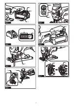
Page 2: ...2 1 2 3 Fig 1 1 2 Fig 2 1 Fig 3 2 1 Fig 4 1 2 Fig 5 1 Fig 6 2 1 Fig 7...

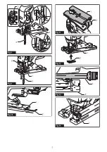
Page 3: ...3 1 3 4 2 Fig 8 1 2 3 Fig 9 1 2 Fig 10 1 2 Fig 11 2 1 Fig 12 1 2 Fig 13 1 Fig 14...

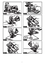
Page 4: ...4 1 2 Fig 15 1 2 Fig 16 Fig 17 3 1 2 Fig 18 1 2 3 6 5 4 Fig 19 3 1 2 Fig 20 Fig 21 Fig 22...

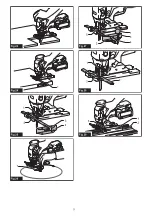
Page 5: ...5 Fig 23 1 Fig 24 4 2 1 3 Fig 25 1 Fig 26 1 2 3 4 5 Fig 27 1 2 3 Fig 28 1 2 3 Fig 29...

Page 6: ...tended for the sawing of wood plastic and metal materials Noise The typical A weighted noise level determined accord ing to EN62841 2 11 Sound pressure level LpA 90 dB A Sound power level LWA 98 dB A...

Page 7: ...workpiece 6 Check for the proper clearance around the workpiece before cutting so that the jig saw blade will not strike the floor workbench etc 7 Hold the tool firmly 8 Make sure the jig saw blade i...

Page 8: ...eries Use of non genuine Makita batteries or batteries that have been altered may result in the battery bursting causing fires personal injury and damage It will also void the Makita warranty for the...

Page 9: ...ita Service Center Selecting the cutting action This tool can be operated with an orbital or a straight line up and down cutting action The orbital cutting action thrusts the jig saw blade forward and...

Page 10: ...ch the pre set speed NOTE When the temperature is low this function may not be available This function also may not be available depending on the type of the material NOTE If the speed does not decrea...

Page 11: ...splintering device onto the cover plate Fig 12 1 Base 2 Anti splintering device Dust extraction Optional accessory The dust nozzle is recommended to perform clean cutting operations To attach the dus...

Page 12: ...f 170 mm or less in radius install the rip fence as follows Fig 26 1 Rip fence Guide rule CAUTION Do not touch the tip of the circular guide pin The sharp tip of the circular guide pin can cause injur...

Page 13: ...or attachment for its stated purpose If you need any assistance for more details regard ing these accessories ask your local Makita Service Center Jig saw blades Hex wrench 4 Rip fence guide rule set...

Page 14: ...le bois le plastique et les m taux Bruit Niveau de bruit pond r A typique d termin selon EN62841 2 11 Niveau de pression sonore LpA 90 dB A Niveau de puissance sonore LWA 98 dB A Incertitude K 3 dB A...

Page 15: ...m talliques expos es de l outil lectrique et lectrocuter l utilisateur 2 Utilisez des dispositifs de serrage ou un autre moyen pratique pour fixer la pi ce sur une surface de travail stable La pi ce s...

Page 16: ...l emballage 11 Lors de la mise au rebut de la batterie reti rez la de l outil et jetez la en lieu s r Suivez les r glementations locales en mati re de mise au rebut des batteries 12 Utilisez les batte...

Page 17: ...lie possible de la batterie NOTE Selon les conditions d utilisation et la tem p rature ambiante l indication peut tre l g rement diff rente de la capacit r elle NOTE Le premier t moin compl tement gau...

Page 18: ...nc le commu tateur de verrouillage pour permuter entre les trois niveaux de luminosit NOTE La luminosit de la lampe ne peut pas tre ajust e alors que l outil est en mode veille Pour r gler la luminosi...

Page 19: ...r rapidement apr s le rel chement de la g chette faites r parer l outil dans un centre de service Makita ASSEMBLAGE ATTENTION Assurez vous toujours que l outil est hors tension et que sa batterie est...

Page 20: ...ccord poussi re Fig 15 1 Raccord poussi re 2 Tuyau pour l aspirateur UTILISATION ATTENTION Tenez toujours la base au ras de la pi ce Sinon la lame de scie sauteuse risque de se briser ce qui pourrait...

Page 21: ...la goupille du guide circulaire La pointe ac r e de la goupille du guide circulaire est source de blessure 1 Ins rez le guide parall le dans l orifice rectan gulaire sur le c t de la base avec le gui...

Page 22: ...lles ils ont t con us Pour obtenir plus de d tails sur ces accessoires contactez votre centre d entretien local Makita Lames de scie sauteuse Cl hexagonale 4 Ensemble du guide parall le r gle de guida...

Page 23: ...stoff und Metallmaterial vorgesehen Ger usch Typischer A bewerteter Ger uschpegel ermittelt gem EN62841 2 11 Schalldruckpegel LpA 90 dB A Schallleistungspegel LWA 98 dB A Messunsicherheit K 3 dB A HIN...

Page 24: ...Kabel k nnen die freiliegenden Metallteile des Elektrowerkzeugs ebenfalls Strom f hrend werden so dass der Benutzer einen elektrischen Schlag erleiden kann 2 Verwenden Sie Klemmen oder eine andere pra...

Page 25: ...er Spediteure m ssen besondere Anforderungen zu Verpackung und Etikettierung beachtet werden Zur Vorbereitung des zu transportierenden Artikels ist eine Beratung durch einen Experten f r Gefahrengut e...

Page 26: ...bis die rote Anzeige nicht mehr sichtbar ist Anderenfalls kann er aus dem Werkzeug herausfallen und Sie oder umstehende Personen verletzen VORSICHT Unterlassen Sie Gewaltanwendung beim Anbringen des...

Page 27: ...ten Abb 4 1 Sperrschalter 2 Lampe Die Helligkeit hat drei Stufen Um die Helligkeit der Lampe zu ndern halten Sie den Sperrschalter gedr ckt wenn Sie die Lampe einschalten Ca 1 Sekunde nach dem Gedr ck...

Page 28: ...f 1 Die Lampe blinkt zweimal wenn die Nulllast Sanfthubfunktion deaktiviert oder aktiviert ist Um diese Funktion wieder zu aktivieren oder zu deaktivieren f hren Sie das gleiche Verfahren erneut durch...

Page 29: ...wird empfohlen um saubere Schneidvorg nge durchzuf hren Um den Absaugstutzen am Werkzeug zu befestigen f hren Sie den Haken des Absaugstutzens in das Loch in der Grundplatte ein Abb 13 1 Absaugstutzen...

Page 30: ...ten werden gew hrleistet der Parallelanschlag schnelle saubere und gerade Schnitte Abb 24 1 Parallelanschlag Richtlineal Setzen Sie den Parallelanschlag zur Montage so in das Vierkantloch an der Seite...

Page 31: ...dendienstzentren unter ausschlie licher Verwendung von Makita Originalersatzteilen ausgef hrt werden SONDERZUBEH R VORSICHT Die folgenden Zubeh rteile oder Vorrichtungen werden f r den Einsatz mit dem...

Page 32: ...teriali metallici Rumore Livello tipico di rumore pesato A determinato in base allo standard EN62841 2 11 Livello di pressione sonora LpA 90 dB A Livello di potenza sonora LWA 98 dB A Incertezza K 3 d...

Page 33: ...o e causare una scossa elet trica all operatore 2 Utilizzare una morsa o un altro sistema pratico per fissare e supportare il pezzo in lavorazione su un piano stabile Il pezzo mantenuto con la mano o...

Page 34: ...dall utensile e smaltirla in un luogo sicuro Attenersi alle normative locali relative allo smaltimento della batteria 12 Utilizzare le batterie esclusivamente con i prodotti specificati da Makita L i...

Page 35: ...lla batteria Premere il pulsante di controllo sulla cartuccia della batteria per indicare la carica residua della batteria Gli indicatori luminosi si illuminano per alcuni secondi Fig 2 1 Indicatori l...

Page 36: ...pi basso e ripete la riduzione Quando si raggiunge la luminosit desiderata rilasciare l interruttore di blocco In tal modo si dispone anche l utensile in modalit standby AVVISO Quando l utensile surr...

Page 37: ...e di regolazione della velo cit su 6 1 6 Freno elettrico Questo utensile dotato di un freno elettrico Qualora l utensile non riesca ripetutamente ad arrestarsi rapi damente dopo il rilascio dell inter...

Page 38: ...lveri Accessorio opzionale La bocchetta polveri consigliata per eseguire opera zioni di taglio pulite Per montare la bocchetta polveri sull utensile inserire il gancio della bocchetta polveri nel foro...

Page 39: ...are la guida di taglio per assicurare dei tagli rapidi puliti e diritti Fig 24 1 Guida di taglio righello guida Per installare la guida di taglio inserirla nel foro rettan golare sul lato della base c...

Page 40: ...ori o compo nenti aggiuntivi sono consigliati per l uso con l u tensile Makita specificato nel presente manuale L impiego di altri accessori o componenti aggiuntivi pu costituire un rischio di lesioni...

Page 41: ...A gewogen geluidsniveaus zijn gemeten volgens EN62841 2 11 Geluidsdrukniveau LpA 90 dB A Geluidsvermogenniveau LWA 98 dB A Onzekerheid K 3 dB A OPMERKING De opgegeven geluidsemissiewaar de n is zijn...

Page 42: ...er spanning komen te staan zodat de gebruiker een elektrische schok kan krijgen 2 Gebruik klemmen of andere bevestigingsmid delen om het werkstuk op een stabiel platform te bevestigen en te ondersteun...

Page 43: ...Gebruik de accu s uitsluitend met de gereed schappen die door Makita zijn aanbevolen Als de accu s worden aangebracht in niet compatibele gereedschappen kan dat leiden tot brand bui tensporige warmteo...

Page 44: ...etreden Gereedschap accubeveiligingssysteem Het gereedschap is voorzien van een gereedschap accubeveiligingssysteem Dit systeem schakelt auto matisch de voeding naar de motor uit om de levensduur van...

Page 45: ...staat Om de helderheid aan te pas sen schakelt u het gereedschap uit en daarna weer in OPMERKING De lamp wordt ingeschakeld op het zelfde helderheidsniveau als de laatste keer dat het gereedschap wer...

Page 46: ...l stilstaat nadat de trekkerschakelaar is losgelaten laat u het gereedschap onderhouden door een Makita servicecentrum MONTAGE LET OP Zorg altijd dat het gereedschap is uitgeschakeld en de accu ervan...

Page 47: ...op de stofafzuigaansluitmond Fig 15 1 Stofafzuigaansluitmond 2 Slang van de stofzuiger BEDIENING LET OP Houd de zool altijd vlak met het oppervlak van het werkstuk Als u dat niet doet bestaat de kans...

Page 48: ...gt aan Fig 26 1 Breedtegeleider liniaal LET OP Raak de punt van de cirkelgeleider pen niet aan De scherpe punt van de cirkelgeleider pen kan letsel veroorzaken 1 Steek de breedtegeleider in de rechtho...

Page 49: ...n uitsluitend voor hun bestemde doel Wenst u meer bijzonderheden over deze acces soires neem dan contact op met het plaatselijke Makita servicecentrum Decoupeerzaagbladen Inbussleutel 4 Breedtegeleide...

Page 50: ...dera pl stico y metal Ruido El nivel de ruido A ponderado t pico determinado de acuerdo con la norma EN62841 2 11 Nivel de presi n sonora LpA 90 dB A Nivel de potencia sonora LWA 98 dB A Error K 3 dB...

Page 51: ...corriente puede hacer que la corriente circule por las partes met licas expuestas de la herramienta el ctrica y soltar una descarga el c trica al operario 2 Utilice mordazas u otros medios de sujeci...

Page 52: ...de bater a ret relo de la herramienta y des chelo en un lugar seguro Siga los reglamentos locales referentes al desecho de la bater a 12 Utilice las bater as solamente con los produc tos especificados...

Page 53: ...bater a restante Las l mparas indicadoras se iluminan durante unos pocos segundos Fig 2 1 L mparas indicadoras 2 Bot n de comprobaci n L mparas indicadoras Capacidad restante Iluminada Apagada Parpade...

Page 54: ...n Libere el interruptor de bloqueo cuando alcance al brillo deseado Esto tambi n pone la herramienta en el modo de espera AVISO Cuando la herramienta est recalentada la l mpara parpadea Deje enfriar l...

Page 55: ...suave sin carga cambiando el dial de ajuste de velocidad a 6 1 6 Freno el ctrico Esta herramienta est equipada con un freno el ctrico Si la herramienta consistentemente deja de pararse r pidamente de...

Page 56: ...mienta inserte el gancho de la boquilla de polvo en el agujero de la base Fig 13 1 Boquilla de polvo 2 Base Para sujetar la boquilla de polvo apriete el tornillo de fijaci n de la parte frontal de la...

Page 57: ...ta la posici n de la anchura de corte deseada despu s apriete el perno para sujetarla Fig 25 1 Llave hexagonal 2 Perno 3 Orientador de gu a lateral 4 Gu a lateral Regla gu a Cortes circulares Cuando c...

Page 58: ...o de heridas personales Utilice el accesorio o aditamento solamente con la finalidad indicada para el mismo Si necesita cualquier ayuda para m s detalles en relaci n con estos accesorios pregunte al c...

Page 59: ...met licos Ru do A caracter stica do n vel de ru do A determinado de acordo com a EN62841 2 11 N vel de press o ac stica LpA 90 dB A N vel de pot ncia ac stica LWA 98 dB A Variabilidade K 3 dB A NOTA O...

Page 60: ...urar na pe a de trabalho com a m o ou contra o corpo deixa a inst vel e pode levar perda de controlo 3 Utilize sempre culos de seguran a Os cu los normais ou de sol N O s o culos de seguran a 4 Evite...

Page 61: ...de ficar suficientemente quente para provocar queimaduras 16 N o permita a ades o de aparas p ou suji dade nos terminais nos orif cios e nas ranhu ras da bateria Poder fazer com que a ferra menta ou a...

Page 62: ...do a ferramenta ou a bateria estiver sobreaque cida a ferramenta para automaticamente e a l mpada pisca Neste caso deixe a ferramenta e a bateria arre fecerem antes de ligar novamente a ferramenta Pro...

Page 63: ...te e a l mpada apaga NOTA Tamb m pode parar e desligar a ferramenta ao pressionar o interruptor de bloqueio enquanto a ferramenta estiver a funcionar Indicador de ajuste da velocidade Fig 6 1 Indicado...

Page 64: ...o da serra para contornar move se para a posi o fixa por si mesma e a serra para contornar fica bloqueada Certifique se de que a extremidade traseira da serra para contornar encaixa no rolo Puxe ligei...

Page 65: ...nfro atrav s de gradua es Em seguida aperte firmemente o perno para fixar a base Fig 19 1 Ranhura de chanfro 2 Base 3 Perno 4 Gradua es 5 Entalhe em V 6 Caixa de transmiss o Cortes face dianteiros Sol...

Page 66: ...a da r gua no orif cio quadrado da base at ao fim Fixe o perno firmemente com a chave sextavada Fig 28 1 Chave sextavada 2 Barra da r gua 3 Perno Insira a barra da r gua no orif cio quadrado do adapta...

Page 67: ...135 mm 10 mm 20 mm BL4025 283 mm D C 36 V 40 V 2 6 2 9 kg EPTA 01 2014 BL4020 BL4025 BL4040 BL4040F DC40RA DC40RB DC40RC DC40WA EN62841 2 11 LpA 90 dB A LWA 98 dB A 3 dB A EN62841 2 11 ah B 4 6 m s 2...

Page 68: ...68 A 1 2 3 4 5 6 7 8 9 10 11 12 13 14 15...

Page 69: ...69 1 1 2 3 2 3 4 5 1 2 3 6 50 C 7 8 9 10 11 12 Makita 13 14 15 16 17 18 Makita Makita Makita Makita 1 2 3 10 C 40 C 4 5...

Page 70: ...70 1 1 2 3 2 1 2 75 100 50 75 25 50 0 25...

Page 71: ...71 1 2 3 Makita 3 1 0 I II III 4 1 2 1 5 1 2 10 6 1 6 1...

Page 72: ...72 4 6 3 6 3 4 3 6 1 4 6 1 6 1 3 1 2 1 3 4 6 1 6 1 6 Makita...

Page 73: ...73 7 1 2 8 1 2 3 4 9 1 2 3 III 10 1 2 11 1 2 12 1 2 13 1 2 14 1 Makita 15 1 2 16 1 2 0 45 17...

Page 74: ...74 18 1 2 3 V 19 1 2 3 4 5 V 6 20 1 2 3 12 mm 21 22 1 2 3 4 23 160 mm 24 1 25 1 2 3 4 170 mm 26 1 1 2 27 1 2 3 4 5 3 B 17 B 18 B 26 B 27...

Page 75: ...75 28 1 2 3 29 1 2 3 B 8 B 13 B 16 B 17 58 Makita Makita Makita Makita 4 Makita...

Page 76: ...llan m amac Bu alet ah ap plastik ve metal malzemeleri kesmek amac yla kullan l r G r lt Tipik A a rl kl g r lt d zeyi EN62841 2 11 standar d na g re belirlenen Ses bas n seviyesi LpA 90 dB A Ses g c...

Page 77: ...zl k DE LD R 4 ivi kesmekten ka n n leme ba lamadan nce i par as n kontrol edip ivi varsa kar n 5 ok b y k par alar kesmeyin 6 Kesmeden nce i par as n n etraf nda deku paj testere b a n n zemine al ma...

Page 78: ...y ksek gerilim elektrik g hatlar yak n nda kullan m desteklemedi i s rece batarya kartu unu y ksek gerilim elektrik g hatlar n n yak n nda kullanmay n Aletin veya batarya kartu unun ar zalanmas na ve...

Page 79: ...durur ve lamba yan p s ner Bu durumda yeniden al t rmadan nce aletin ve bataryan n so umas n bekleyin A r de arj korumas Batarya kapasitesi yeterli olmad nda alet otomatik olarak durur Bu durumda bata...

Page 80: ...a n n hizmet mr k sal r par as Rakam Ah ap 4 6 Yumu ak elik 3 6 Paslanmaz elik 3 4 Al minyum 3 6 Plastik 1 4 NEML NOT H z ayar kadran yaln zca 6 e kadar ve geriye 1 e kadar evrilebilir 6 i veya 1 i ge...

Page 81: ...AT Alet a c y ok fazla a may n aksi takdirde aletin hasar g rmesine neden olabilir Dekupaj testere b a n karmak i in alet a c y ileri do ru sonuna kadar a n Bu dekupaj testere b a n n b rak lmas n sa...

Page 82: ...n Kesiminize ba lamak i in dekupaj testere b a n bu deli e yerle tirin ek 21 Dik kesim A a da anlat lanlar dikkatlice uygularsan z bir ba lang deli i delmeniz ya da bir giri kesimi yapman z gerekmez...

Page 83: ...7 veya 58 numaral dekupaj testere b aklar n kullan n BAKIM D KKAT Muayene ya da bak m yapmadan nce aletin kapal ve batarya kartu unun kart l m oldu undan daima emin olun NEML NOT Benzin tiner alkol ve...

Page 84: ...Makita Europe N V Jan Baptist Vinkstraat 2 3070 Kortenberg Belgium Makita Corporation 3 11 8 Sumiyoshi cho Anjo Aichi 446 8502 Japan 885982D992 EN FR DE IT NL ES PT EL TR 20231218...

Reviews: