


P 3 /13
[3] DISASSEMBLY/ASSEMBLY
[3] -1. Tool Retainer
R
epair
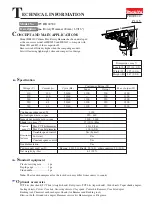
Cut-off wheel
Model 4030C
Assemble Tool retainer to Tool holder using arbor press as illustrated in Fig. 3
.
Model 4041C
1) Mount Tool retainer on Tool holder. (Fig. 2A)
2) Fasten M8x12 Hex bolt securely to Tool retainer through Compression spring 5. (Fig. 2A)
Note: Be sure to apply threadlocker to the threaded portion of M8x12 Hex bolt.
The recommended threadlocker is Loctite 603 or Threebond 1303B.
3) Assemble Cap to Tool holder while fitting the two projections on Cap in the notch of Tool holder. (Fig. 3A)
Angle grinder
Tool retainer
Tool holder
center line of
the two holes
Tool holder
Tool holder
work bench
Tool retainer
Fig. 2
Fig. 2A
Model 4030C
Damaged Tool retainer can be disassembled from Tool holder by cutting it into two using Angle grinder or the like
as illustrated in Fig. 2.
Model 4041C
1) Remove Cap from Tool holder by hand. (Fig. 2A)
2) By unscrewing M8x12 Hex bolt, Tool retainer and Compression spring 15 can be disassembled from Tool holder.
(Fig. 2A)
Note: Threadlocker is applied to the thread portion of M8x12 Hex bolt.
Tool retainer
Hex bolt M8x12
Compression spring 15
Cap
Tool holder
projection
notch
Cap
ASSEMBLING
DISASSEMBLING
HR4030C
HR4041C
Fig. 3
Fig. 3A
HR4030C
HR4041C
arbor press
Be sure to place the side nearer
to the centerline of the two holes
on work bench.


