


P 7 /13
R
epair
Slide plate
Rubber ring 18
Washer 17
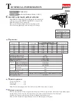
Cylinder A
(viewed from X)
The structure of Cylinder A
Removing Rubber Ring 18
Removing Slide Plate
Removing Washer 17
Cylinder A
Fig. 15
Fig. 17
Fig. 18
Fig. 19
Fig. 16
First, slide Slide plate in the direction of the arrow
until it stops to make a space for removing
Rubber ring 18, Flat washer 17 and Slide plate itself.
Turn Rubber ring 18 so that
it can be seen through the
elliptic hole of Cylinder A
as illustrated below.
Washer 17 can be removed in the same way
as you did in Removing Rubber Ring 18.
Now can be removed
through the hole.
Rubber ring 18
Rubber ring 18
Tilt Slide plate in the direction of
the arrow until it stops.
Slide plate
4) Disassemble Cylinder A as illustrated in Fig. 15 to Fig. 19.
[3] DISASSEMBLY/ASSEMBLY
[3] -3. Cylinder Section (cont.)
DISASSEMBLING
X
Slide plate
Washer 17
Washer 17
Slide plate can now be removed in the same way
as you did in Removing Rubber Ring 18.


