background image

[3] DISASSEMBLY/ASSEMBLY

[3]-2. Impact bolt, Striker (cont.)

ASSEMBLING

Fig. 8

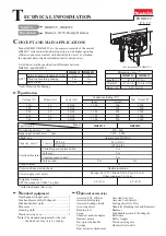
(1) Assemble O rings and Fluoride rings to Impact bolt as drawn in 

Fig. 8

.

1R214

Assembly of Rings to Impact Bolt

Correction

Insert Impact bolt from

the HR4000C side of 

1R214. And keep 

Impact bolt approx. 

60 seconds in 1R214.

Impact bolt

Wrong

Correct

Before Correction:

Rings' edges are protruding from

the top edge of the groove on

Impact bolt.

groove on Impact bolt

Be careful about the assembly direction

of Impact bolt when inserting it into 

Tool holder.

Fluoride ring 25

O ring 20

O ring 20

After Correction:

Rings' edges are positioned under 

the top edge of the groove on 

Impact bolt.

Corrected

R

epair

P  

6

19

Fig. 9

2. Assemble the parts drawn below to Cylinder. Be careful

    about the assembly directions of Ring 17 and Slide sleeve.

1. Insert Striker into Cylinder so that

    the O ring 22 side faces to Piston 

    in Crank housing.

(2) Assemble Striker section as drawn in 

Fig. 9

.

(3) Assemble Barrel section to Cylinder. Refer to 

Fig. 6

.

Cylinder

Ring 17

Correct

Wrong

Rubber ring 18

Slide 

sleeve

Compression spring 33

O ring 22

Striker

Cylinder

1R312

Summary of Contents for HR4013C

Page 1: ...Scoop Side handle assembly D shaped Chemical anchor adaptor Bit Grease Hammer grease Safety Goggle Bar style side handle Plastic carrying case Syringe Hammer Service Kit Dust extractor attachment W H...

Page 2: ...ning Ring S 8 Ring spring removing jig 1R306 removing Crank shaft Retaining ring S and R pliers Spring fixing jig 1R400 disassembling Cylinder from Crank housing 1R350 disassembling Cylinder from Cran...

Page 3: ...portion Inner periphery of Plane bearing 54 78a The component of Crank housing complete Fig 2 Grease R No 00 96 Crank housing and Motor section 20g 20g a little a little 10g a little 44 O ring 30 3 p...

Page 4: ...ing 25 using 1R003 and 1R212 3 Remove Ring 28 Chuck cover Rubber ring 30 Chuck ring and Release cover from Tool holder 4 Remove a pair of Tool retainer by pressing down Spring guide Then separate Spri...

Page 5: ...and Housing cover complete together from Crank housing complete by grabbing and lifting up the chuck by hand Fluoride ring 25 the worn one 3 Insert a long bar into Chuck and then push out Impact bolt...

Page 6: ...he assembly direction of Impact bolt when inserting it into Tool holder Fluoride ring 25 O ring 20 O ring 20 After Correction Rings edges are positioned under the top edge of the groove on Impact bolt...

Page 7: ...le section by unscrewing six 4x25 Tapping screws 1 Reserve the insertion slit for a slotted screwdriver between Guard 40 and Handle base for HR4013C by pressing Handle section toward Crank housing sid...

Page 8: ...ve Spiral bevel gear 26 from Crank housing carefully so as not to be tilted Fig 14 When Spiral bevel gear 26 is tilted in Crank housing in the disassembly process it is impossible to remove Spiral bev...

Page 9: ...nder section is disassembled as drawn in Fig 16 3 DISASSEMBLY ASSEMBLY 3 3 Crank housing Cylinder Counter weight cont Repair P 9 19 Fig 15 Fig 16 Flat washer 33 Compression spring 34 Retaining ring EX...

Page 10: ...11 Connecting rod with Piston section can be removed from Cylinder side Disassemble Piston section Fig 22 3 DISASSEMBLY ASSEMBLY 3 3 Crank housing Cylinder Counter weight cont Fig 17 Fig 19 Fig 21 Fig...

Page 11: ...not to cause misalignment between the pin of Crank shaft and the hole of Connecting rod Fig 24 5 Turn Crank housing upside down and put 1R165 between Arbor press table and Ball bearing 6004LLU then f...

Page 12: ...must be lubricated with Makita grease No R 00 Fig 2 of 2 LUBRICATION When Cylinder is pressfit into Crank housing Put 1R032 under the four pins on handle side of Crank housing as drawn in Fig 28 Place...

Page 13: ...h case set and Control plate are set in place while facing the mark of POM xxxx on Control plate to the upper side pass the projection of Crank lever through the rounded opening of Control plate pass...

Page 14: ...lete Once it is disassembled it is impossible reassemble them again Gear housing Plastic hammer Torque limiter assembly Retaining ring S 8 Ball bearing 608DDW Ball bearing 6002LLU 3 DISASSEMBLY ASSEMB...

Page 15: ...gs from Carbon brushes and put them aside Check that Carbon brushes are detached from Commutator of Armature Fig 42 5 Tap Armature shaft and then pull Crank housing and Gear housing to remove them fro...

Page 16: ...1 1 8 3 7 N m 3 0 3 5 N m M6 Hex nut Fig 49 114 M6 Hex nut 12 M6x30 Hex socket head bolt 4 pcs 75 M2x25 Tapping screw 4 pcs Gear housing complete Barrel complete 4 Maintenance When replacing Carbon b...

Page 17: ...Connector Connector Power supply cord White Red Fig D 1 Controller Terminal block with Line filters Circuit diagram Blue Switch Dial Brown lead wire is used for some countries Blue lead wire is used...

Page 18: ...nit Fix the Lead wires of Lead unit with Lead wire holder Route one Lead wire between Rib A and Boss the other between Rib B and Boss Route Lead wires of Switch unit between Ribs C and D Route Lead wi...

Page 19: ...tor Fix Lead wires connected to Connector in each Lead wire holder Note Do not put Lead wires on or over Ribs and the inner wall of Motor housing Do not put Lead wires on or over the inner wall of Mot...

Reviews: