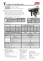


Arbor press
1R032
Crank housing
Two pins
Four pins
Two pins
R
epair
P 1
2
/
19
(7) When Seal ring 8 is removed from Crank housing, be sure to fit Seal ring 8 into the groove of Crank housing before
setting Link plate in place.
Fit Seal ling 8 into the groove of Crank housing especially around Link plate, and pass Link plate through the slot in
Seal ring 8 from the opposite in advance to make space for the smooth installation of Link plate. Their ways will make
it easy to set Link plate in place later. (
Fig. 26
)
(8) Spiral bevel gear 26 must be installed straight. (
Fig. 27
) Do not fail to apply Makita grease No. R 00 to the gear teeth.
(9) Three pieces of O ring 30 on Cylinder must be lubricated with Makita grease No. R 00. (
Fig. 2
of [2] LUBRICATION)
When Cylinder is pressfit into Crank housing, Put 1R032 under the four pins on handle side of Crank housing as drawn
in
Fig. 28
. Place Guide ring in Crank housing as drawn in
Fig. 29
. Be careful about the direction of Guide ring.
Insert the hooks of Link plate into the center groove of Driving sleeve, and install them into Crank housing. (
Fig. 30
)
At this time;
•
engage the gear teeth of Spiral bevel gear 26 and the cam groove of Driving sleeve.
• pass Link plate through the slot of Seal ring 8.
[3] DISASSEMBLY/ASSEMBLY
[3]-3. Crank housing, Cylinder, Counter weight (cont.)
Fig. 28
Fig. 26
Fig. 27
Fig. 30
Fig. 29
Link plate
Slot of Seal ring 8
Apply Makita grease No. R 00 to
the gear teeth of Spiral bevel gear 26.
Wide notch of
Guide ring
Cylinder section
Four pins
Center groove of
Driving sleeve
Hooks of Link plate


