background image

P 8 / 9

C

ircuit diagram

Field

*Noise suppressor is not used for some country. 

Switch

Color index of lead wires' sheath

When Terminal block is used

Fig. D-1

When Terminal block is not used

Fig. D-2

Fig. D-3

Black

P

o

wer supply cord

Field

Switch

P

o

wer supply cord

Terminal block

White

Orange

Yellow

Color index of lead wires' sheath

Black

Noise suppressor*

W

iring diagram

[1] Motor housing

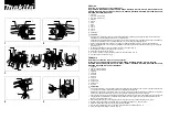
Route Field lead wires as illustrated below. (Fig. D-3)

Field lead wire

(yellow/orange

 or black/white)

Lead wire from

Brush holder

(if used)

Motor housing

Summary of Contents for GA5010

Page 1: ...No load speed min 1 rpm Diameter Hole diameter Wheel size mm Protection against electric shock Power supply cord m ft Net weight kg lbs GA5010 GA5020 GA6010 GA6020 125 5 150 6 Australia Brazil 2 0 6 6...

Page 2: ...020 GA6020 1R005 Retaining ring pliers RT 2N Removing Retaining ring R 30 Installation of Large spiral bevel gear 1 GA5010 GA6010 1R030 Bearing setting pipe 25 17 2 1R036 Bearing setting plate 17 2 Re...

Page 3: ...1 Lubricate the gear and Armature shaft with spray lubricant 2 Wrap the gear with cloth to protect the gear teeth 3 Using water pump pliers or the like firmly grip the gear wrapped with cloth then tur...

Page 4: ...the end of Gear housing with plastic hammer as illustrated in Fig 9 It is not necessary to remove Carbon brushes 2 Remove Ball bearing 6000ZZ using 1R269 Fig 10 Regarding steps 3 and 4 do the alterna...

Page 5: ...ecurely by hand and pull off Lock sleeve with adjustable wrench while turning it counterclockwise Then remove Lock spring 16 the same way as you removed Lock sleeve Fig 14 Fig 16 Fig 17 Ball bearing i...

Page 6: ...use removed Ring spring 7 if it is not damaged Do not forget to fasten Ring spring 7 securely to Spindle using pliers whether it is removed one or new one Note 2 Do as described in Fig 19 when assembl...

Page 7: ...ig 20 DISASSEMBLING Do the reverse of the disassembling steps Note Do not reinstall removed Pin cap because removal of Shoulder pin 5 damages the inside surface of Pin cap Be sure to remove plastic du...

Page 8: ...al block is not used Fig D 2 Fig D 3 Black Power supply cord Field Switch Power supply cord Terminal block White Orange Yellow Color index of lead wires sheath Black Noise suppressor Wiring diagram 1...

Page 9: ...erminals on the Lead wires connected to Switch in order to prevent them from touching the inside wall of Handle Put Terminal block in this portion Lead wire holder Insulated terminal Insulated termina...

Reviews: