background image

2

English

(Original instructions)

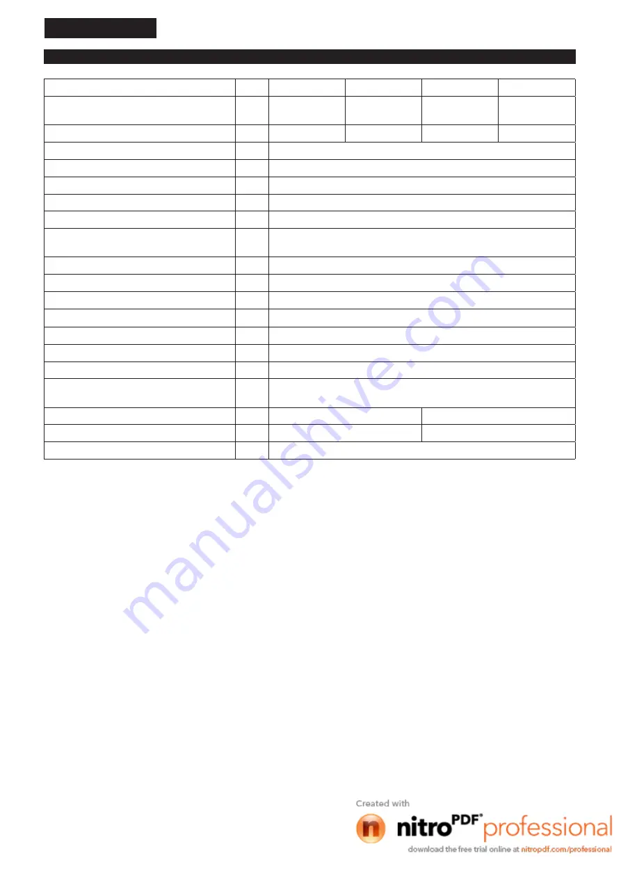
TECHNICAL DATA

Model

EM2510LH

EM2511LH

EM2510LHC

EM2511LHC

Dimensions: length x width x height (without 
cutting tool)

mm 1,757 x 368 x 286 1,766 x 368 x 286 1,757 x 305 x 302 1,766 x 305 x 302

Weight (without plastic guard and cutting tool)

kg

5.3

5.4

5.3

5.4

Engine type

Air cooled, 4-stroke, single cylinder

Volume (fuel tank)

L

0.5

Volume (oil tank)

L

0.08

Engine displacement

cm

3

24.5

Maximum engine performance

kw

0.71 at 7,000 min

-1

Engine speed at recommended max. spindle 
speed

min

-1

8,500

Maximum spindle speed (corresponding)

min

-1

6,500

Idling speed

min

-1

3,000

Clutch engagement speed

min

-1

3,750

Carburetor

Diaphragm type

Spark plug

type

NGK CMR4A

Electrode gap

mm

0.7 - 0.8

Fuel

Automobile gasoline (petrol)

Engine Oil

API grade SF class or higher, SAE 10W-30 oil

(automobile 4-stroke engine oil)

Cutting tool diameter (with metal blade)

mm

230

Cutting tool diameter (with nylon cutting head)

mm

420

420

Gear ratio

14/19

•  Due to our continuing program of research and development, the specifications herein are subject to change without notice.

•  Specifications may differ from country to country.

Summary of Contents for EM2510LH

Page 1: ...Petrol Brushcutter Petrol String Trimmer EM2510LH EM2510LHC EM2511LH EM2511LHC INSTRUCTION MANUAL ...

Page 2: ...in 1 Engine speed at recommended max spindle speed min 1 8 500 Maximum spindle speed corresponding min 1 6 500 Idling speed min 1 3 000 Clutch engagement speed min 1 3 750 Carburetor Diaphragm type Spark plug type NGK CMR4A Electrode gap mm 0 7 0 8 Fuel Automobile gasoline petrol Engine Oil API grade SF class or higher SAE 10W 30 oil automobile 4 stroke engine oil Cutting tool diameter with metal ...

Page 3: ...verage Applicable standard LPA eq dB A Uncertainty K dB A LWA eq dB A Uncertainty K dB A Nylon cutting head 92 9 2 9 110 6 1 3 ISO 22868 Vibration model EM2510LH EM2511LH Left hand Right hand Applicable standard ahv eq m s2 Uncertainty K m s2 ahv eq m s2 Uncertainty K m s2 Metal blade 5 2 1 7 5 0 1 3 ISO 22867 Nylon cutting head 5 0 1 7 6 0 1 5 Vibration model EM2510LHC EM2511LHC Left hand Right h...

Page 4: ... stop ON START OFF STOP Never use metal blade Flying object hazard Keep distance Kickback Fuel Gasoline First Aid You will note the following symbols when reading the instructions manual SYMBOLS Wear sturdy boots with nonslip soles Steeltoed safety boots are recommended Read instruction manual and follow the warnings and safety precautions Keep the area of operation clear of all persons and pets 1...

Page 5: ... bushes or shrubs In order to avoid either head eye hand or foot injuries as well as to protect your hearing the following protective equipment and protective clothing must be used during operation Always wear a helmet where there is a risk of falling objects The protective helmet 1 is to be checked at regular intervals for damage and is to be replaced at the latest after 5 years Use only approved...

Page 6: ...hcutter onto dry grass or onto any combustible materials Always install the approved cutting tool guard onto the equipment before starting the engine Otherwise contact with the cutting tool may cause serious injury All protective installations and guards supplied with the machine must be used during operation Never operate the engine with faulty exhaust muffler Shut off the engine during transport...

Page 7: ...is thrown sideway or toward the operator at great force and it may cause serious injury Kickback occurs particularly when applying the blade segment between 12 and 2 o clock to solids bushes and trees with 3 cm or larger diameter To avoid kickback Apply the segment between 8 and 11 o clock Never apply the segment between 12 and 2 o clock Never apply the segment between 11 and 12 o clock and betwee...

Page 8: ...ing tools and fixing devices of cutting tools or accessories First Aid In case of accident make sure that a first aid box is available in the vicinity of the cutting operations Immediately replace any item taken from the first aid box When asking for help please give the following information Place of accident What happened Number of injured persons Kind of injuries Your name For European countrie...

Page 9: ...l accessory 11 Shaft 12 Protector cutting tool guard 13 Gear case 14 Shoulder harness 15 Blade cover optional accessory 16 Exhaust muffler 17 Air cleaner 18 Starter knob 19 Exhaust pipe 20 Fuel tank cap 21 Recoil starter 22 Oil gauge 23 Fuel tank Note Type of the protector and the cutting tool varies depending on the countries 17 18 20 21 23 22 19 16 14 1 2 3 4 5 6 7 8 9 10 11 12 13 15 ...

Page 10: ...fter deciding the position tighten the bolt Make sure the handle locates between the arrow mark and the spacer WARNING Do not remove or shrink the spacer The spacer keeps a certain distance between both hands Setting the handle close to the other grip beyond the length of the spacer may cause loss of control and serious personal injury Removing or installing the barrier optional accessory WARNING ...

Page 11: ...r is constant Otherwise the protector may not function as expected To meet the applicable safety provisions only the tool protector combinations as indicated in the table must be used Use of metal blade Metal blade Clamp washer cup and nut are necessary Protector Use with barrier Use with shoulder harness Use of nylon cutting head Nylon cutting head Protector 1 3 2 4 For metal blade Fix the protec...

Page 12: ...d for type B protector CAUTION Take care not to injure yourself on the cutter for cutting the nylon cord Fix the protector 1 to the clamp 2 with two bolts M6 x 25 3 with hex wrench 5 4 Installing the metal blade or nylon cutting head CAUTION Be sure to use genuine MAKITA cutter blades or nylon cutting head The cutter blade must be well polished free of cracks or breakage If the cutter blade hits a...

Page 13: ...rench To remove the metal blade perform as follows 1 Insert the hex wrench through the hole in the gear case and rotate the receiver washer until it is locked with the hex wrench 2 Loosen the nut clockwise with the socket wrench and remove the nut cup clamp washer and hex wrench NOTE The cutter blade fastening nut with spring washer wears out in course of time Replace the nut if there appears any ...

Page 14: ...upright oil may go into around the engine and may be refilled excessively If the oil is filled above the limit the oil may be contaminated or may catch fire with white smoke Point 1 in Replacement of oil Oil gauge Remove dust or dirt near the oil refill port and detach the oil gauge Keep the detached oil gauge free of sand or dust Otherwise any sand or dust adhering to the oil gauge may cause irre...

Page 15: ... by tilting the fuel tank so that the refuel port will be oriented upward Never refill fuel full to the oil refill port Wipe well the periphery of the tank cap to prevent foreign matter from entering into the fuel tank After refueling securely tighten the tank cap If there is any flaw or damage on the tank cap replace it The tank cap is consumable and therefore should be renewed every two to three...

Page 16: ...e buckle to release the tool Be extremely careful to maintain control of the machine at this time Do not allow the machine to be deflected toward you or anyone in the work vicinity Correct posture Adjust the harness length so that the cutter blade will be kept parallel with the ground WARNING Always position the tool on your right hand side Correct positioning of the tool allows for maximum control...

Page 17: ...vention regulations Starting Move at least 3 m away from the place of refuelling Place the Petrol Brushcutter on a clean piece of ground taking care that the cutting tool does not come into contact with the ground or any other objects A Cold start 1 Set this machine on a flat space 2 Set the I O switch 1 to operation position 3 Close the choke lever Choke opening Full closing in cold or when the en...

Page 18: ... start knob until it returns to its original point 6 Choke lever When the engine starts open the choke lever Open the choke lever progressively while checking the engine operation Be sure to open the choke lever to the full in the end In cold or when the engine is cooled down never open the choke lever suddenly Otherwise the engine may stop 7 Warm up operation Continue warm up operation for 2 to 3...

Page 19: ...ing the spark plug Always wear protective gloves To ensure a long service life and to avoid any damage to the equipment the following servicing operations should be performed at regular intervals Daily checkup and maintenance Before operation check the machine for loose screws or missing parts Pay particular attention to the tightness of the cutter blade or nylon cutting head Before operation alwa...

Page 20: ...lowing procedure 1 Confirm that the tank cap is tightened securely 2 Detach the oil gauge Keep the oil gauge free from dust or dirt Fuel tank cap Oil gauge Waste or paper 3 Place waste or paper near the oil refill port POINTS ON OIL Never discard replaced engine oil in garbage earth or sewage ditch Disposal of oil is regulated by law In disposal always follow the relevant laws and regulations For ...

Page 21: ...ner may fall outside resulting in oil contamination CLEANING OF FUEL FILTER WARNING INFLAMMABLES STRICTLY PROHIBITED Interval of Cleaning and Inspection Monthly every 50 operating hours Suction head in the fuel tank The fuel filter 1 of the suction head is used to filter the fuel required by the carburetor A periodical visual inspection of the fuel filter is to be conducted For that purpose open t...

Page 22: ...TS NUTS AND SCREWS Retighten loose bolts nuts etc Check for fuel and oil leakage Replace damaged parts with new ones for safety operation CLEANING OF PARTS Keep the engine always clean Keep the cylinder fins free of dust or dirt Dust or dirt adhering to the fins will cause piston seizure Fuel pipe REPLACEMENT OF GASKETS AND PACKINGS In reassembling after the engine is dismounted be sure to replace...

Page 23: ...left hand direction indicated by LH and right hand direction by RH on the side of the spool Wind all but about 100 mm 3 15 16 of the cords leaving the ends temporarily hooked through a notch on the side of the spool Mount the spool in the housing so that the grooves and protrusions on the spool match up with those in the housing Keep the side with letters on the spool visible on the top Now unhook...

Page 24: ...ord or 2 0 mm 0 08 diagonal square cord Align the arrow on the spool with the eyelets on the housing Insert one end of the nylon cord into eyelet on the side of the housing feed through hole on top of the spool and then re insert into the second hole on top of the spool Push the nylon cord into holes until the cord feeds through eyelets on side of the housing Push the nylon cord into holes feeding...

Page 25: ...e spool in the direction marked on the head for left hand direction indicated by LH Cover Latches Press Press 80 mm For left hand rotation Spool Wind all but about 100 mm of the cords leaving the ends temporarily hooked through a notch on the side of the spool 100 mm Notches Align the protrusion on the underside of the cover with the slots of the eyelets Then push cover firmly onto the housing to ...

Page 26: ...of the spool Wind all but about 100 mm 3 15 16 of the cords leaving the ends temporarily hooked through a notch on the side of the spool Mount the spool in the housing so that the grooves and protrusions on the spool match up with those in the housing Keep the side with letters on the spool visible on the top Now unhook the ends of the cord from their temporary position and feed the cords through ...

Page 27: ...e the machine to prevent the machine from falling Otherwise it may result in personal injury Keep the drained fuel in a special container in a well ventilated shade Drain fuel Humidity STORAGE Attention after long time storage Before startup after long time shutdown be sure to replace oil refer to P 20 Oil will deteriorate while the machine is kept out of operation Fault System Observation Cause E...

Page 28: ...h 30h 50h 200h Shutdown rest Engine oil Inspect Replace 1 Tightening parts bolt nut Inspect Fuel tank Clean inspect Drain fuel 3 Throttle lever Check function Stop switch Check function Cutting blade Inspect Low speed rotation Inspect adjust Air cleaner Clean Ignition plug Inspect Cooling air duct Clean inspect Fuel pipe Inspect Replace 2 Gear case grease Refill Fuel filter Clean replace Clearance...

Page 29: ...mal carburetor Make request for inspection and maintenance Starter rope cannot be pulled Make request for inspection and maintenance Abnormal drive system Make request for inspection and maintenance Engine stops soon Engine speed does not increase Insufficient warm up Perform warm up operation Choke lever is set to CLOSE although engine is warmed up Set to OPEN Clogged fuel filter Clean or replace...

Page 30: ...30 ...

Page 31: ...31 ...

Page 32: ...885498A226 ALA www makita com Makita Europe N V Makita Corporation 3 11 8 Sumiyoshi cho Anjo Aichi 446 8502 Japan Jan Baptist Vinkstraat 2 3070 Kortenberg Belgium ...

Reviews: