
6-18
Engine block (cont. - Piston section)
6-18-1
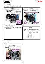
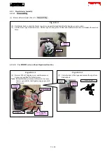
Replacing
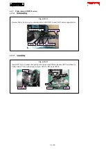
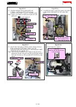
Fig. 6-18-1-1
[1] Pinch one end of Clip (2 pcs.) with thin long nose
pliers, and slide it out of the groove of Piston.
Note:
Remove the other Clip from the opposite, in the same
way.
Groove of Piston
Thin long nose
pliers
Clip
Piston
Clip
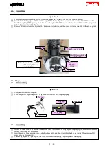
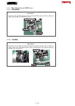
Fig. 6-18-1-2
[2] Push out Piston pin with a bit of Cordless impact driver
or a rod.
Piston pin
a rod/ bit
Clip (2 pcs.)
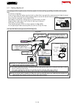
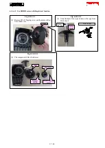
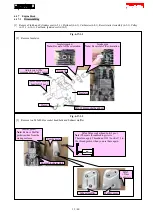
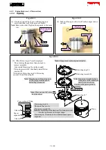
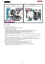
Fig. 6-18-1-3
[3] When Piston ring set* must be replaced:
·
Do not enlarge the gap more than you need to
remove/ assemble.
·
First, install Piston ring 34, and then, install
Piston ring (second) 34, then finally install Piston
ring (top) 34.
*It consists of Piston ring (top) 34, Piston ring
(second) 34 and Piston ring 34.
Note:
All gaps must not be aligned vertically.
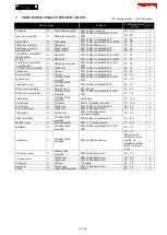
Piston ring (top) 34
Piston ring (second) 34
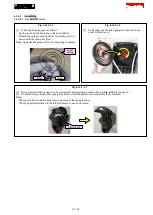
Note:
Piston ring (second) 34 has a
white paint on the right upper
end if it is not worn out.
Face the white paint upward in
assembly.
White paint
Piston ring 34*
Piston
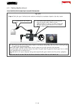
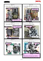
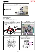
Note:
Place the gap of Piston ring (top)
34 180° away from the gap of
Piston ring (second) 34.
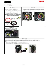
Note:
Place one gap 120° away
from the others.
Cross section of Piston
Side rail*
Spacer
expander*
Side rail*
Piston ring (top) 34
The center has a curve.
Piston ring (second) 34
Note:
Be careful about the direction. The bottom is wider
than the top because of the taper shape.
Piston ring 34: It consists of Two Side rails and Spacer
expander.
36 / 40


