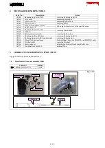
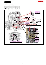
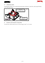
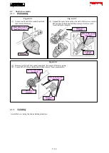

6-4-1-2
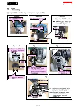
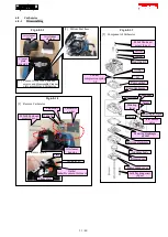
Assembling
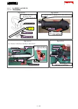
[1] Assemble by reversing the disassembling procedure.
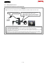
Fig. 6-4-1-2-1
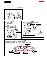
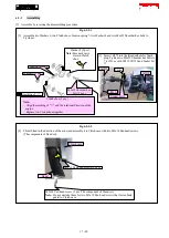
[2] Assemble
Lock-off lever
to Lever case L.
[7] Assemble Throttle
lever to Lever case
L.
[4] Set
Corrugate
tube in the
unit.
Route the lead wires
through the hole.
Set the lead wires
into each lead holder.
[5] Assemble
Control cable to
Throttle lever.
[8] Assemble Cable holder.
Cable holder
Corrugate
tube
Stop switch lead
wires must have a
margin of 25-30mm.
[3] Assemble Torsion spring 7 to
Lock off lever.
[9] Assemble Switch lever to
Switch cover.
Hang the spring on the rib.
[6] Assemble Torsion spring 11 to
Throttle lever.
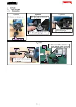
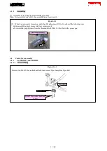
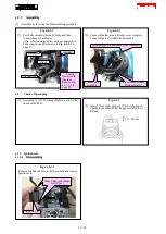
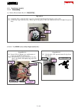
Fig. 6-4-1-2-2
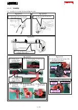
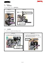
[10] To prevent Lever case R from contacting Leaf
spring, assemble Leaf spring to Switch lever in
parallel.
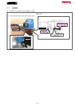
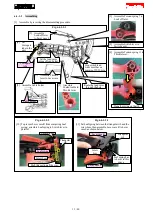
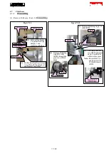
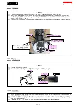
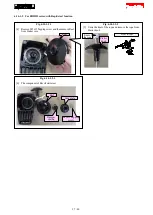
Fig. 6-4-1-2-3
[11] Set Leaf spring between the triangular rib and the
screw boss, then assemble Lever case R to Lever
case L as shown below.
Lever case R
Triangular
rib
Screw
boss
Lever case L
Leaf spring has
to be set in this
space.
Leaf spring
Switch lever
Push this section all the way.
Triangular
rib
Screw boss
12 / 40


