9 ENGLISH
NOTE:
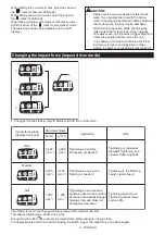
During the operation of switch trigger, the impact force grade cannot be changed.
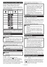
Changing the torque setting
(screwdriver mode)
The fastening torque can be adjusted by pressing the
button
in screwdriver mode.
The numbers on the LED display shows torque setting.
The fastening torque is minimum at the number 1 and
maximum at the number 9. The indication "P" is a spe-
cial mode for fastening self drilling screws.
Every time the button
is pressed, the torque setting
changes from 1 to 9 and P, and then returns to 1.
The torque setting changes fast by keeping pressing
the button.
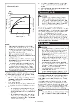
P mode is suitable for fastening self drilling screws into
steel plates in the following conditions.
•
With speed change lever at "2" side, fastening
max. 4 mm screw into total max. 3.2 mm steel
plates.
•
With speed change lever at "1" side, fastening
max. 5 mm screw.
Before an actual operation, drive a trial screw into
your material or a piece of duplicate material to deter
-
mine which torque level is required for a particular
application.
First, try to fasten the screw at "1". Then increase the
number to continue fastening. Hold the tool firmly during
operation.
CAUTION:
Don't fasten the machine screw on P
mode. It may twist your wrist suddenly and result in
personal injury.
NOTE:
•
Make sure to check the number on LED display
before operation. If the number is not indicated,
contact your nearest Makita service center.
•
When the remaining battery capacity gets low
in the screwdriver mode, the light flashes a few
times when fastening the screw completely. In
this case, recharge the battery. If you keep oper
-
ating, you may not obtain the desired torque.
•
During pulling the switch trigger, the torque
setting cannot be changed.
•
For approximately one minute after releasing
the switch trigger, the torque setting can be
changed. if you want to change the torque set
-
ting after that, pull the switch trigger again.
•
The number of torque setting does not mean
specific torque rate.
Empty signal for remaining battery
capacity
(Country specific)
►
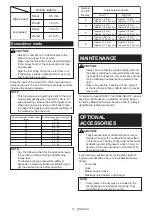
Fig.10:
1.
Battery capacity
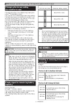
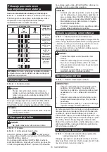
The remaining battery capacity will be signaled on the
LED display when pulling the switch trigger.
The remaining battery capacity is shown as the follow
-
ing table.
LED indicator status
Remaining battery capacity
About 50% or more
About 20% - 50%
About less than 20%
NOTE:
•
When the LED display goes off, the tool is turned
off to save the battery power. To check the remain
-
ing battery capacity, slightly pull the switch trigger.
•
The LED display goes off approximately one
minute after releasing the switch trigger.
•
When the temperature of the tool gets high, the light flashes
once per second for one minute, and then the LED display
goes off. In this case, cool down the tool before operation.
ASSEMBLY
CAUTION:
•
Always be sure that the tool is switched off and
the battery cartridge is removed before carrying
out any work on the tool.
Installing or removing driver/drill/
socket bit
►
Fig.11
Use only the driver/drill/socket bit shown in the figure.
Do not use any other driver/drill/socket bit.
For tool with shallow bit hole
A=12 mm
B=9 mm
Use only these type of bit. Follow the
procedure (1).
(Note) Bit-piece is not necessary.
For tool with deep bit hole
To install these types of bits, follow
the procedure (1).
To install these types of bits, follow
the procedure (2).
(Note) Bit-piece is necessary for
installing the bit.
A=17 mm
B=14 mm
A=12 mm
B=9 mm


