


July 2015
5.
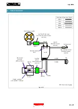
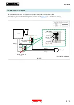
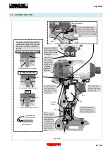
WIRING DIAGRAM
5.1.
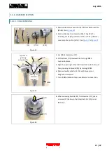
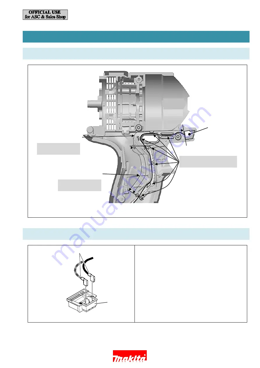
LED SECTION
Figure 41
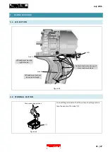
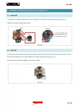
5.2.
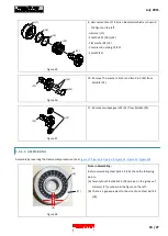
TERMINAL SECTION
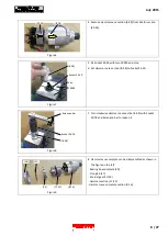
Connect Flag terminal so that the wire connecting portions
face the center of Terminal (7).
Figure 42
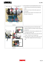
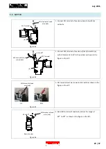
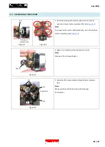
Wire connecting portions
LED Lead wires must be
tight in Area A.
LED
Area A
Area B
LED Lead wires must not
be crossed in Area B.
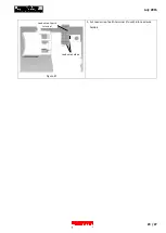
Put these Lead wires into any of
these Lead wire holders.
(7)
21 / 27