


July 2015
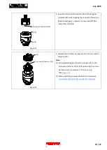
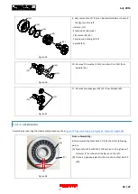
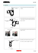
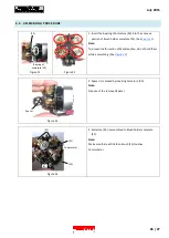
8. Insert Carbon brush (31) into Brush holder complete (32).
Shift the tail of Torsion spring from the Notch of Brush
holder complete (32) to the top of Carbon brush (31).
Carbon brush (31) is locked with the pressure of Torsion
spring.
Note: When shifting Torsion spring’s tail, hold Torsion
spring not to fall off from Brush holder complete
(32).
Figure 26
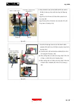
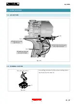
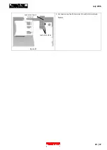
9. Fit the concave portion of F/R change lever (5) to the
projection of Switch unit (6).
Figure 27
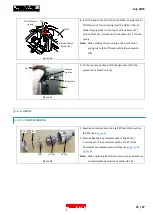
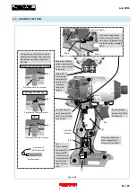
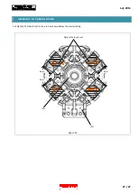
3.3.3.
ANVIL
3.3.3.1.
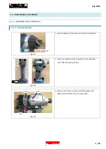
DISASSEMBLING
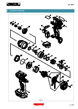
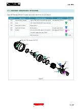
1. Remove Hammer case section (8-28) from Motor section
(29-33). (See
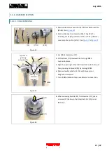
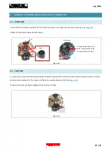
2. Remove Bearing box complete (28), O ring 40 (27),
Internal gear 51 (26), Hammer section (17-25) from
Hammer case complete section (8-16). (See
Note: When repairing Bit holder section only, you need not
to disassemble Hammer case section (8-28).
Figure 28
Concave
portion
Projection
(5)
(6)
(28)
(27)
(26)
(17-25)
(8-16)
Notch of Brush
holder (32)
(32)
(31)
Tail of Torsion
spring
15 / 27