background image

P 14/ 22

R

epair

[3] DISASSEMBLY/ASSEMBLY

[3]-5. Tool holder section of  DHR263

          Tool holder guide section of DHR264 (cont.)

ASSEMBLING

DISASSEMBLING

Fig. 28

(1) Assemble Spur gear 51, Compression spring 32 and Washer 31 to Tool holder (guide). (

Fig. 27

(2) Using repairing jigs of 1R249 and 1R369, secure the parts with Ring spring 29. (

Fig. 27

)

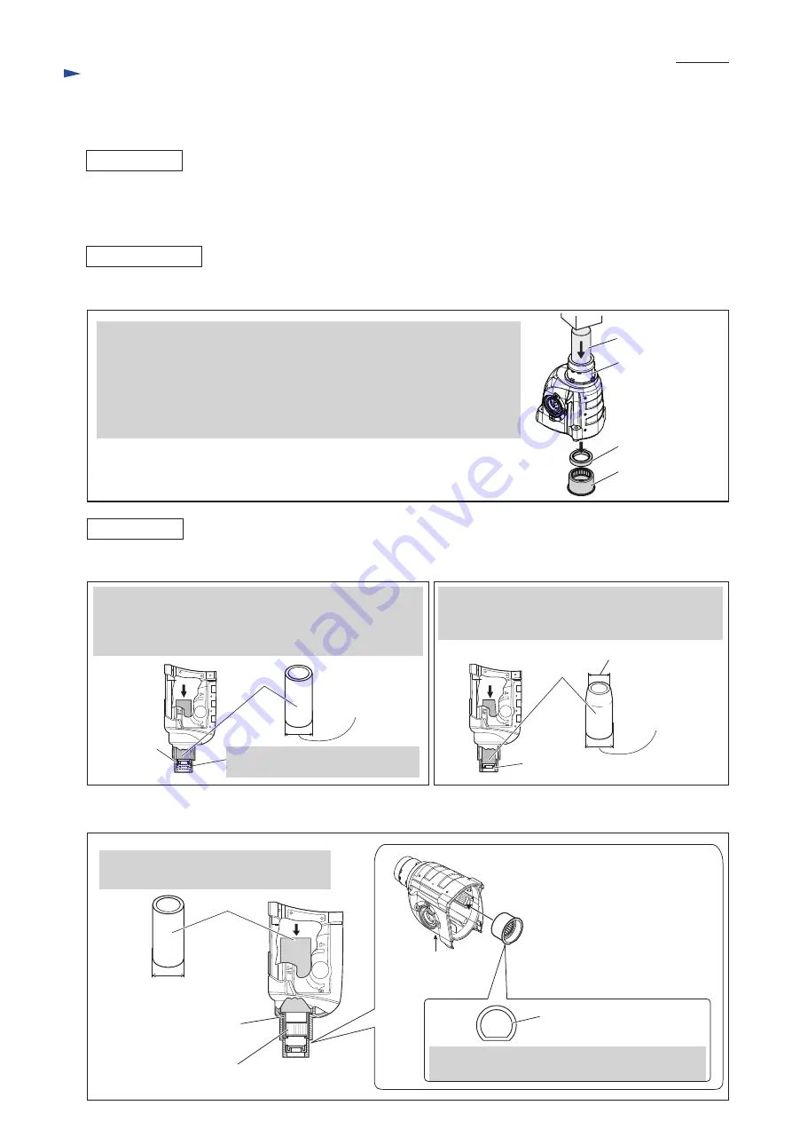
Put Gear housing complete on Arbor press table, and keep it upright. Then,

by pressing down Oil seal 25 using 1R252, Oil seal 25 and Needle bearing

complete can be removed from Gear housing complete 

with gentle pressure

.

Note

: On Arbor press table, Gear housing complete can stand almost upright

          on its end edges. Although the end edges are rather thin, you need not

          worry about breakage because Oil seal 25 and Needle bearing complete

          are fitted to Gear housing complete with low press fit force. 

1R252

Oil seal 25

Gear housing

complete

Needle bearing

complete

[3]-6. Needle bearing complete and Oil seal 25

(1) Assemble Oil seal 25 to Gear housing complete. (

Figs. 29

 and 

30

)

Disassemble Needle bearing complete. (

Fig. 28

)

1R164

Outer diameter: 30mm

Outer 

Diameter: 34mm

Oil seal 25

With 1R232 and Arbor press, insert Oil seal 25 until it stops.

In this step, Oil seal 25 is not yet inserted completely

because the outer diameter of 1R232 is larger than that of

Oil seal setting hole.  

original position of Oil seal 25

Fig. 29

Fig. 30

Using Arbor press and the 34mm outer diameter end

of 1R164, press down Oil seal 25 until it stops at its

original position. 

ASSEMBLING

Fig. 31

(2) Assemble Needle bearing complete. (

Fig. 31

)  

Outer diameter: 30mm

1R165

With 1R165 and Arbor press, press down

Needle bearing complete until it stops.

Needle bearing portion of

Needle bearing complete

Cup washer portion of

Needle bearing complete

Face the flat portion of Needle bearing complete

towards the bottom side of Gear housing complete.

bottom side of

Gear housing

complete

Needle bearing complete

[view from rear side]

Note

1) Do not use 1R164 in this step.

2) Do not press

 Needle bearing

     portion

 directly.

3) Too much pressure will deform

     Needle bearing complete.

     Do not press hard.

4) Be sure to press 

Cup washer

    portion

 with gentle pressure.     

1R232

Outer 

diameter: 36mm

The diameter of Oil seal 25 setting 

hole is smaller than 36mm.  

Summary of Contents for DHR263

Page 1: ...ion with hammering Hammering only 0 1 250 0 5 000 Adapted for SDS PLUS bits Adapted for SDS PLUS bits and Round shank bits 1 Capacity of Quick change chuck mm N A 1 5 1 16 13 1 2 26 1 54 2 1 8 Max out...

Page 2: ...cup 9 Dust extractor attachment Grease vessel 30g Bit grease Blow out bulb Hammer Service Kit Battery BL1815N Battery BL1820 Battery BL1830 Battery BL1840 Battery BL1850 Fast charger DC18RC Charger D...

Page 3: ...88 removing Ring spring 28 Retaining ring S and R pliers removing Retaining ring WR 12 from Armature shaft Gear extractor large 2 LUBRICATION Apply the following grease to protect parts and product fr...

Page 4: ...where Swash bearing section rotates c Gear portion a Oil seal 25 on the inside of Gear housing complete Entire surface Inside where Piston cylinder reciprocates Impact bolt Impact bolt Cushion ring 1...

Page 5: ...lder guide complete 3 Separate Chuck cover Then remove Steel ball 7 0 while pressing down Stopper Chuck cover Steel ball 7 0 Stopper Stopper Change ring Change cover Ring spring 21 Torsion spring 31 T...

Page 6: ...lder to Change cover Fig 8 Fig 8 Change cover Change ring 2 By turning Tool holder approx 75 clockwise Tool holder can be fastened to Change cover Tool holder 75 1 Insert the long arm of Torsion sprin...

Page 7: ...her 24 Leaf spring and Steel ball 5 0 can be removed Pull off Change cover Change ring and Torsion spring 31 can be removed Torsion spring 31 Chuck holder Spacer Chuck holder Chuck holder Chuck holder...

Page 8: ...to Chuck holder then secure them with Ring spring 21 Fig 18 Spacer Spacer Spacer 1 Insert the short arm of Torsion spring 31 into the hole of Chuck holder using pliers Fitting Chuck holder s flat por...

Page 9: ...and Gear housing complete then pry up Change lever Drill mode Lock button Change lever DISASSEMBLING Fig 19 Fig 20 thick pin of Change lever Hammer mode thin pin of Change lever ASSEMBLING Fig 21 Cha...

Page 10: ...need to remove two 4x18 Tapping screws that fasten Handle R to Handle L DISASSEMBLING of Motor section 3 Remove two Pins 6 and Handle section from Housing L to disassemble Motor section Then Remove Co...

Page 11: ...enough care Ball bearing 6001DDW on the drive end of Armature may often be incompletely seated in the bearing room of Inner housing Therefore fit the bearing completely into the bearing room in Inner...

Page 12: ...be replaced Pin 6 2pcs Handle R Handle L Switch Assemble Switch to Handle L by reversing the disassembly procedure Refer to Fig 26 4x18 Tapping screw 2 pcs Fig 26 1 Remove two 4x40 Tapping screws tig...

Page 13: ...holder ass y with a plastic hammer Gear housing complete can be removed Note Grease falls from Gear housing complete Receive it with waste cloth Flat washer 28 Piston Cylinder Tool holder guide sectio...

Page 14: ...le bearing complete Fig 28 1R164 Outer diameter 30mm Outer Diameter 34mm Oil seal 25 With 1R232 and Arbor press insert Oil seal 25 until it stops In this step Oil seal 25 is not yet inserted completel...

Page 15: ...r guide complete slide it with a slotted screwdriver until it is completely hidden 4 Put 1R388 into Tool holder guide complete then push 1R388 in vise with the access holes on Tool holder guide comple...

Page 16: ...te as drawn in Fig 36 Note 1 Use an extra Piston cylinder as a jig Never use Piston cylinder that is to be assembled to the machine 2 The end gap of Ring spring 28 must not be positioned in either of...

Page 17: ...n in Fig 42 then press down Cam shaft using 1R281 to loosen the press fit of Cam shaft to Spiral bevel gear 26 Ball bearing 608ZZ and Ring 8 at a time Fig 42 Also Clutch cam Swash bearing 10 Sleeve 9...

Page 18: ...e plate then Piston joint to Piston cylinder Fig 44 5 Fit Compression spring 14 over the boss of Inner housing Fig 45 6 Insert the pole of Swash bearing 10 through the hole of Piston joint then mount...

Page 19: ...olybdenum disulfide lubricant to the specific portions Refer to Figs 1 2 and 3 Fig 48 DHR263 DHR264 1 Cap 35 286263 4 29 Steel ball 7 0 216022 2 115 Steel ball 7 0 216022 2 35 Cushion ring 13 421955 0...

Page 20: ...1 White Orange Blue Yellow Color index of lead wires sheath Black Red These Line filters are not used for some countries Controller Line filter 10 30 Line filter 2 holes type Switch Housing set L sid...

Page 21: ...wires with these lead wire holders Brush holder Fix Brush holder s lead wires with this Lead wire holder Compression spring 10 Switch Put Closed end splices in here Put Line filters to the place here...

Page 22: ...using set L while facing its Lead wire connected portion to the housing Controller Lead wire connected portion 2 Connect Flag connectors to Terminals while facing the wire connected portions to the ho...

Reviews: