P
5
/
8
R
epair
[3] DISASSEMBLY/ASSEMBLY
[3] -2. Replacing large Spiral Bevel Gear and Ball Bearing 6201DDW (cont.)
ASSEMBLING
Assemble by reversing the disassembly procedure.
Note :
•
Do not forget to put Flat washer 12 in Bearing box. (Refer to
Fig. 10
.)
•
Be careful not to deform Labyrinth ring 19 when assembling to Spindle.
•
Referring to
Fig. 7
, assemble Woodruff key 4, Spiral bevel gear (large) and Wave washer 12 to Spindle.
Then, assemble Retaining ring S-12 using 1R291 by fitting exactly to the groove on Spindle’s drum with snap.
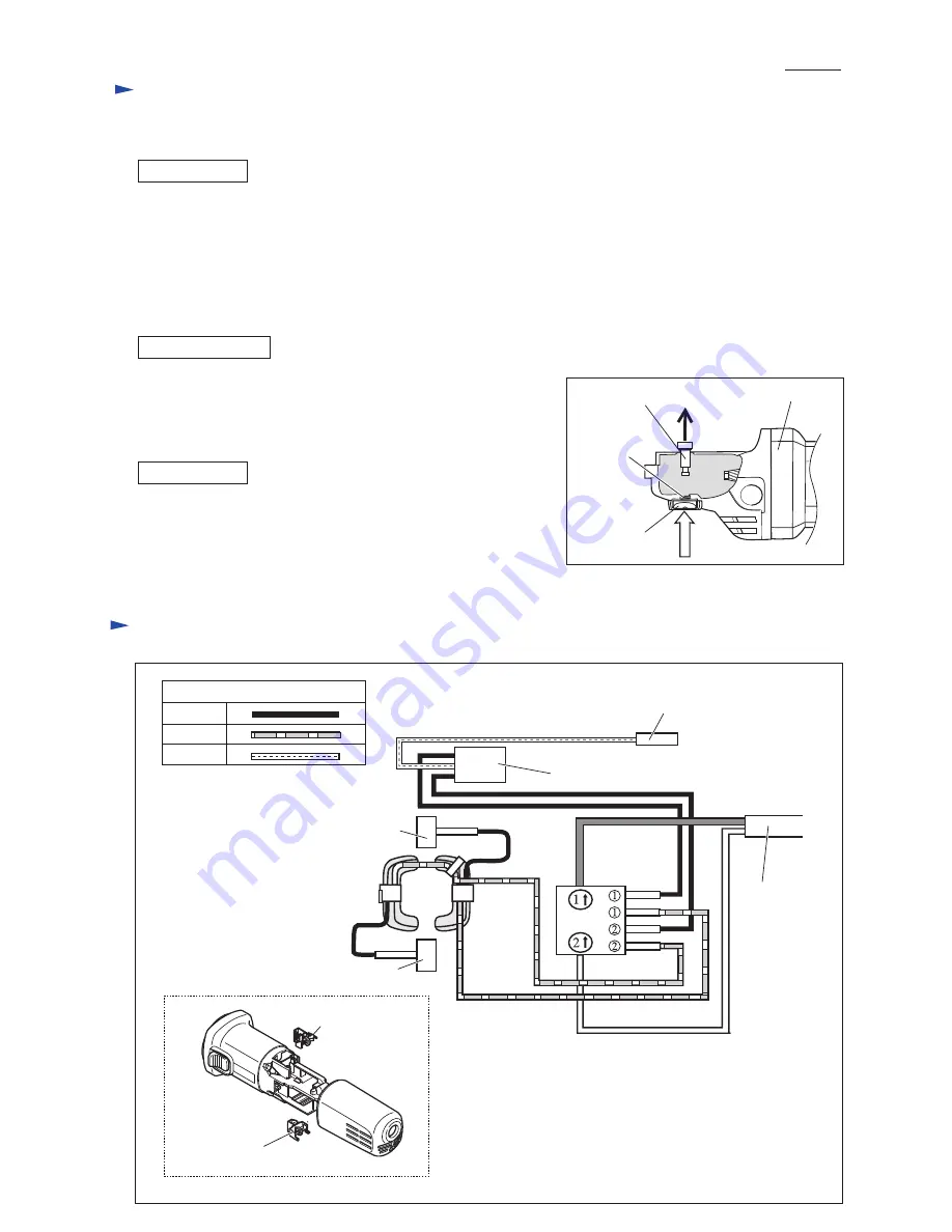
[3] -3. Disassembling/Assembling Shaft Lock Mechanism
(1) Remove Bearing box from Gear housing.
(2) Pull off Shoulder pin 4 with pliers while pushing Pin cap with
finger. (
Fig. 11
)
Note
: Do not pull off Shoulder pin 4 without holding Pin cap
because Compression spring 8 would sling Pin cap.
Push Shoulder pin 4 through Gear housing and
Compression spring 8 into Pin cap.
Note
: Do not reuse removed Pin cap because removal of Shoulder
Pin 4 damages the inside surface of Pin cap, producing plastic dust.
Therefore, be sure to use a new Pin cap for replacement and to remove
all the plastic dust on Shoulder pin 4.
DISASSEMBLING
ASSEMBLING
Fig. D-1
Fig. 11
Pin cap
Gear housing
Shoulder pin 4
Compression
spring 8
C
ircuit diagram
Red
Clear
Color index of lead wires' sheath
Black
Brush holder A
Brush holder A
Noise suppressor*
Earth terminal (Ground terminal)
on the lead wire of Noise suppressor
Power supply
cord
Brush holder B
Brush holder B
Field
Switch
*noise suppressor is not used for some countries.


