W
iring diagram
P
8
/
8
[4] Connecting lead wires (cont.)
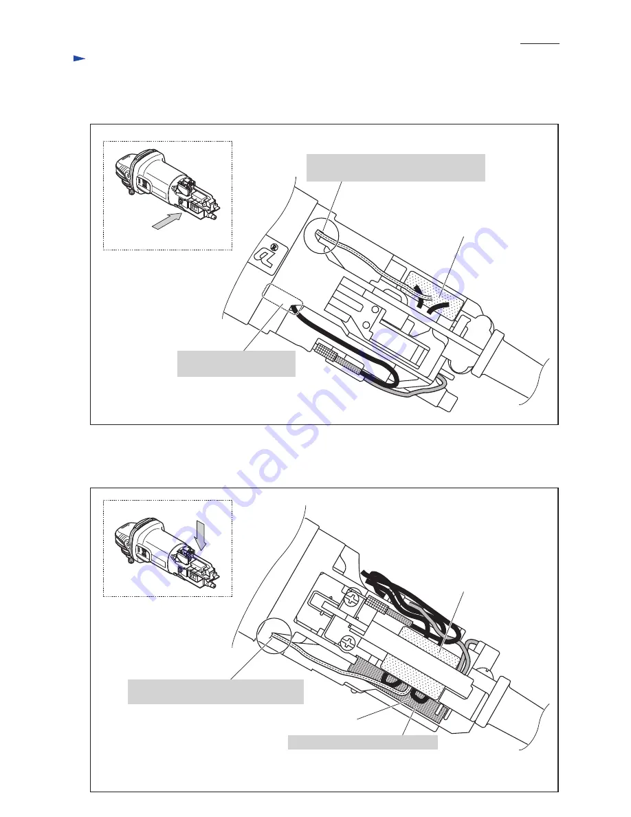
[4] -4. Field lead wires in the rear of Motor housing
[5] Noise suppressor and Sensormatic tag
Fig. D-5
Fig. D-6
*Noise suppressor is not used for some countries.
**Sensormatic tag is not used for some countries.
Sensormatic tag
(anti-theft tag)
Noise suppressor*
Put Sensormatic tag** in this space.
Noise suppressor*
Be sure that Field lead wires
are tight in Motor housing.
Left side view
Top view
Connect Earth terminal on Lead wire (clear)
of Noise suppressor* to this portion.
Connect Earth terminal on Lead wire (clear)
of Noise suppressor* to this portion.
*Noise suppressor is not used for some countries.


