background image

3

ENGLISH 

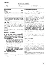
Explanation of general view 

1

Locator 

2

Stopper 

3

Magnetic bit holder 

4

Bit 

5

Locking sleeve 

6

Speed control screw 

7

Switch trigger 

8

Lock button 

9

Reversing switch lever 

SPECIFICATIONS 

Model 6820V

Capacities 

Self drilling screw ................................................. 6 mm
Drywall screw  ...................................................... 5 mm
Driving shank .................................................. 1/4” Hex

No load speed (min

–1

)  ...................................... 0 – 4,000

Overall length  ..................................................... 268 mm
Net weight .............................................................. 1.3 kg

• Due to our continuing program of research and devel-

opment, the specifications herein are subject to change
without notice. 

• Note: Specifications may differ from country to country. 

Power supply 

The tool should be connected only to a power supply of
the same voltage as indicated on the nameplate, and can
only be operated on single-phase AC supply. They are
double-insulated in accordance with European Standard
and can, therefore, also be used from sockets without
earth wire. 

Safety hints 

For your own safety, please refer to the enclosed Safety
instructions. 

SPECIFIC SAFETY RULES

GEB017-1

DO NOT let comfort or familiarity with product
(gained from repeated use) replace strict
adherence to screwdriver safety rules. If you use
this tool unsafely or incorrectly, you can suffer
serious personal injury.

1.

Hold power tools by insulated gripping surfaces
when performing an operation where the cutting
tool may contact hidden wiring or its own cord.

Contact with a “live” wire will make exposed metal
parts of the tool “live” and shock the operator.

2.

Always be sure you have a firm footing. Be sure
no one is below when using the tool in high loca-
tions. 

3.

Hold the tool firmly. 

4.

Keep hands away from rotating parts. 

5.

Do not touch the bit or the workpiece immedi-
ately after operation; they may be extremely hot
and could burn your skin. 

SAVE THESE INSTRUCTIONS. 

WARNING:
MISUSE or failure to follow the safety rules stated
in this instruction manual may cause serious per-
sonal injury.

OPERATING INSTRUCTIONS 

Removing or installing the bit (Fig. 1) 

Important:
Always be sure that the tool is switched off and
unplugged before removing or installing the bit. 

To remove the bit, first pull the stopper out of the locator.
Then grasp the bit with a pair of pliers and pull the bit out
of the magnetic bit holder. Sometimes, it helps to wiggle
the bit with the pliers as you pull. To install the bit, push
the bit firmly into the magnetic bit holder. Then install the
stopper by pushing it firmly into the locator. 

Depth adjustment (Fig. 2, 3 & 4) 

Push the locking sleeve in toward the motor and turn
slightly clockwise to lock it. 

Turn the locator to adjust the depth. Initially, adjust the
locator so that the tip of the locator is flush with the base
of the screw head. One full turn of the locator equals 1.5
mm change in depth. After adjusting the locator, unlock
the locking sleeve. Turn the locking sleeve slightly so that
the protrusions on the locking sleeve engage in the
notches in the locator. Drive a trial screw into your mate-
rial or a piece of duplicate material. If the depth is not
suitable for the screw, continue adjusting until the proper
depth setting is obtained. 

NOTE:
Before starting your job, always test-drive a sample
screw into a piece of the installation workpiece so that
you are sure to have the right depth and desired adjust-
ment. 

Switch action (Fig. 5) 

CAUTION:
Before plugging in the tool, always check to see that the
switch trigger actuates properly and returns to the “OFF”
position when released. 

To start the tool, simply pull the trigger.tool speed is
increased by increasing pressure on the trigger. Release
the trigger to stop. For continuous operation, pull the trig-
ger and then push in the lock button. To stop the tool from
the locked position, pull the trigger fully, then release it. A
speed control screw is provided so that maximum tool
speed can be limited (variable). Turn the speed control
screw clockwise for higher speed, and counterclockwise
for lower speed. 

NOTE: 
Even with the switch on and motor running, the bit will not
rotate until you fit the point of the bit in the screw head
and apply forward pressure to engage the clutch. 

Summary of Contents for 6820V

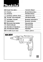
Page 1: ... per l uso NL Drywall schroevendraaier Gebruiksaanwijzing E Atornillador Drywall Manual de instrucciones P Aparafusadora Manual de instruções DK Elektronisk Skruemaskine Brugsanvisning S Gipsskruvdragare Bruksanvisning N Skrutrekker til Gipsskruer Bruksanvisning SF Kiviseinäruuvinväännin Käyttöohje GR Κατσαβίδι ξηρού τοίχου Οδηγίες χρήσεως 6820V ...

Page 2: ...2 1 2 3 4 5 6 7 ...

Page 3: ...rtant Always be sure that the tool is switched off and unplugged before removing or installing the bit To remove the bit first pull the stopper out of the locator Then grasp the bit with a pair of pliers and pull the bit out of the magnetic bit holder Sometimes it helps to wiggle the bit with the pliers as you pull To install the bit push the bit firmly into the magnetic bit holder Then install th...

Page 4: ...e fastened Apply pressure to the tool and start it Withdraw the tool as soon as the screw bottoms out CAUTION Use the proper bit for the head of the screw that you wish to use When fitting the screw onto the point of the bit be care ful not to push in on the screw If the screw is pushed in the clutch will engage and the screw will rotate sud denly This could damage a workpiece or cause an injury N...

Page 5: ... consignes de sécurité du présent manuel d ins tructions peuvent entraîner une grave blessure MODE D EMPLOI Pose et dépose de l embout Fig 1 Important Assurez vous toujours que le contact est coupé et l outil débranché avant de retirer ou d installer l embout Pour enlever l embout retirer d abord la butée du posi tionneur Saisir ensuite l embout à l aide de pinces et sortir l embout du porte embou...

Page 6: ...urface de la pièce à visser Appli quez une pression sur votre outil et faites le tourner Reti rez l outil dès que la vis est complètement introduite ATTENTION Utilisez l embout adapté à la tête de votre vis Quand vous adaptez la vis à l extrémité de l embout faites attention à ne pas appuyer sur la vis Vous ris queriez d enclencher l embrayage et la vis se mettrait brusquement en rotation ce qui r...

Page 7: ...WAHREN SIE DIESE HINWEISE SORGFÄLTIG AUF WARNUNG MISSBRAUCH oder Missachtung der Sicherheits vorschriften in dieser Anleitung können schwere Verletzungen verursachen BEDIENUNGSHIN WEISE Montage bzw Demontage von Schraubendrehereinsätzen Abb 1 Wichtig Vergewissern Sie sich vor der Montage bzw Demontage von Schraubendrehereinsätzen stets daß die Maschine abgeschaltet und der Netzstecker gezogen ist ...

Page 8: ...Schraube ganz eingedreht ist VORSICHT Verwenden Sie übereinstimmende Größen und Typen für Schrauben drehereinsätze und Schraubenköpfe Die Schraube beim Einsetzen auf den Schraubendre hereinsatz nicht andrücken da die Gefahr besteht daß die Kupplung einrastet und die Schraube sich dreht Verletzungen oder Beschädigugen der Werkstückober fläche könnten verursacht werden HINWEIS Den Schraubendreherein...

Page 9: ...tante Sempre assicurarsi che l utensile è staccato dalla presa di corrente e l interrutore è staccato prima di montare oppure smontare la punta Per estrarre la punta innanzitutto tirare il supporto fuori dal locatore A questo punto afferrare la punta con un paio di pinze ed estrarla dal suo supporto magnetico A volte l operazione risulta piú facile se mentre si tira si torce anche la punta con le ...

Page 10: ...uperficie del materiale che si vuole fissare Esercitare pressione sull utensile e metterlo in moto Ritirare l utensile appena la vite raggiunge il fondo ATTENZIONE Usare una punta adatta alla misura della testa della vite di cui si desidera far uso Quando si piazza le vite sul taglio della punta fare attenzione a non esercitare pressione sulla vite Se si esercita pressione sulla vite il mandrino e...

Page 11: ...it de buurt van draaiende onderdelen 5 Raak onmiddellijk na het inschroeven de bit niet aan aangezien deze ontzettend heet kan zijn en brandwonden kan veroorzaken BEWAAR DEZE VOORSCHRIFTEN WAARSCHUWING VERKEERD GEBRUIK of het niet naleven van de vei ligheidsvoorschriften in deze gebruiksaanwijzing kan leiden tot ernstige persoonlijke verwonding BEDIENINGSVOORSCHRIFTEN Verwijderen of installeren va...

Page 12: ...laar alleen in de andere stand nadat het gereedschap volledig tot stilstand is geko men Indien u dit nalaat kan het gereedschap zware beschadiging oplopen Het gereedschap is ook voorzien van een omkeerscha kelaar om de draairichting om te schakelen Zet de omkeerschakelaar op FWD voor draairichting naar rechts en op REV voor draairichting naar links Werkwijze Fig 7 Plaats de kop van de schroef op d...

Page 13: ... de que no haya nadie debajo cuando utilice la herramienta en un lugar alto 3 Sujete firmemente la herramienta 4 Mantenga las manos alejadas de partes girato rias 5 No toque la punta ni la pieza de trabajo inmedia tamente después de la operación porque pue den estar muy calientes y podrían producirle quemaduras GUARDE ESTAS INSTRUCCIONES ADVERTENCIA El MAL USO o el no seguir las normas de segurida...

Page 14: ...e parada Si se cambia la dirección de rotación mientras la herramienta está girando puede averiarse la herramienta Esta herramienta tiene un interruptor inversor para cam biar la dirección de rotacion Mueva la palanca del inte rruptor inversor hacia la posición FWD para rotación hacia la derecha o hacia la posición REV para rotación hacia la izquierda Operación Fig 7 Adapte el tornillo en la punta...

Page 15: ...a ferramenta está desligada e com a ficha retirada da tomada antes de extrair ou colocar o bit Para extrair o bit retire primeiro o batente do regulador de profundidade Em seguida segure o bit com um ali cate e extraia o do porta brocas magnético Para efec tuar esta operação por vezes é necessário rodar um pouco o bit com o alicate Para colocar o bit introduza o com força no porta brocas magnético...

Page 16: ... e ponha a a funcionar Retire a ferramenta logo que o parafuso esteja introduzido PRECAUÇÃO Utilize sempre um bit adequado à cabeça do parafuso que deseje aparafusar Quando colocar o parafuso no bit tenha cuidado para não exercer demasiada pressão porque pode provocar o início involuntário do aparafusamento danificando a superfície de trabalho ou causando danos NOTA Certifique se de que o bit está...

Page 17: ...r slået fra og netledningen taget ud af stikkontakten før De monterer eller afmonte rer værktøj For at fjerne værktøjet trækkes stopperen først ud af føre kappen Tag derefter fat i værktøjet med en tang og træk det ud af den magnetiske værktøjsholder Det kan være en hjælp at vrikke lidt med tangen samtidig med der trækkes Montér værktøjet ved at skubbe det helt ind i den magnetiske værktøjsholder ...

Page 18: ...en Træk maskinen tilbage så snart skruen går i bund OBS Brug kun værktøj bits der passer 100 til den skrue type der anvendes Når skruen sættes på spidsen af værktøjet skal De være omhyggelig med ikke at presse på skruen Hvis værktøjet skubbes ind mens afbryderen er påvirket vil værktøjet kobles til og skruen køre med rundt Dette kan medføre skade på emne eller person BEMÆRK Sørg for at værktøjet s...

Page 19: ...nna bruksanvisning kan orsaka allvarliga personskador BRUKSANVISNING Byte av bits Fig 1 Viktigt Förvissa dig alltid om att maskinen är frånkopplad och att nätkabeln dragits ut ur vägguttaget innan arbete utförs på maskinen För att avlägsna bitset skall Du först dra ut fronthylsan ur djupanslaget Fatta sedan tag i bitset med en tång och drag ut bitset från den magnetiska bitshållaren Det kan ibland...

Page 20: ...en så att inte inkoppling sker och skruven plötsligt börjar rotera mel lan fingrarna OBS Kontrollera att bitset är rakt isatt i skruvhuvudet annars kan skruven och eller bitset skadas UNDERHÅLL VARNING Förvissa dig alltid om att nätkabeln dragits ut ur väggut taget och att maskinen är frånkopplad innan något arbete utförs på maskinen För att bibehålla produktens säkerhet och tillförlitlighet bör a...

Page 21: ...tid etter at verktøyet er slått av og støpslet tatt ut av stikkkontakten før demontering eller montering av bits Bitset demonteres ved først å trekke anleggshylsen ut av dybdestopperen Hold bitset med en tang og trekk den ut av den magnetiske bitsholderen Det kan gjøre demonte ringen lettere hvis bitsen vris fra side til side mens den trekkes ut Bitset monteres ved å skyve den godt inn i den magne...

Page 22: ...bake straks skruen er drevet i OBS Pass alltid på at bitsen passer til skruen som skal dri ves i Når bitsen settes på skruehodet må det ikke øves trykk på skruen Hvis skruen skyves inn vil det medføre at clutchen aktiveres slik at skruen begynner å rotere helt uventet Dette kan igjen forårsake at materialet ødeleg ges eller at det oppstår personskader MARK Sørg alltid for at bitsen ikke settes skj...

Page 23: ...n noudattamatta jättäminen voi aiheuttaa vakavan loukkaantumisen KÄYTTÖOHJEET Terän asennus tai poisto Kuva 1 Huomio Varmista aina ennen terän asennusta tai poistoa että koneesta on katkaistu virta ja se on irrotettu virtaläh teestä Vedä terän irrotusta varten ensin pidin pois kiinnittimestä Ota sitten terästä kiinni pihdeillä ja vedä terä irti teränpiti mestä Pyöritä terää hieman pihdeillä vetäes...

Page 24: ...a aseta ruuvi työstöpinnalle Paina konetta ja käynnistä se Ota kone pois heti kun ruuvi on porautunut paikalleen VAROITUS Käytä ruuville sopivaa terää Kun asetat ruuvin terän kärjelle älä paina sitä Jos ruu via painetaan kytkin käynnistyy ja ruuvi alkaa pyöriä Saatat vaurioittaa työstöpintaa tai itseäsi HUOM Varmista että terä tulee suoraan ruuvin päähän muuten ruuvi ja tai terä asattavat vahingoi...

Page 25: ...τω 1ταν χρησιµοποιείτε το µηχάνηµα σε ψηλά µέρη 3 Κρατάτε το µηχάνηµα σταθερά 4 Κρατάτε τα χέρια σας µακριά απ1 τα περιστρεφ1µενα µέρη 5 Μην αγγίξετε την αιχµή ή το αντικείµενο εργασίας αµέσως µετά τη λειτουργία γιατί µπορεί να είναι εξαιρετικά θερµά και να σας προκαλέσουν εγκαύµατα ΦΥΛΑΞΕΤΕ ΑΥΤΕΣ ΤΙΣ Ο ΗΓΙΕΣ ΠΡΟΕΙ ΟΠΟΙΗΣΗ ΚΑΚΗ ΧΡΗΣΗ ή αµέλεια να ακολουθήσετε τους καν1νες ασφάλειας που περιγράφοντ...

Page 26: ... ταν το µηχάνηµα έχει σταµατήσει εντελώς Αλλαγή της διεύθυνσης περιστροφής του µηχανήµατος πριν αυτ σταµατήσει µπορεί να καταστρέψει το µηχάνηµα Αυτ το µηχάνηµα έχει ένα διακ πτη αντιστροφής για να αλλάζει τη διεύθυνση περιστροφής Μετακινείστε το µοχλ του διακ πτη αντιστροφής στη θέση FWD για δεξι στροφη περιστροφή ή στη θέση REV για αριστερ στροφη Λειτουργία Εικ 7 Εφαρµ στε τη βίδα στο άκρο της α...

Page 27: ...orme agli standard di documenti standardizzati seguenti EN60745 EN55014 EN61000 secondo le direttive del Consiglio 89 336 CEE e 98 37 CE EG VERKLARING VAN CONFORMITEIT Wij verklaren hierbij uitsluitend op eigen verant woordelijkheid dat dit produkt voldoet aan de volgende normen van genormaliseerde documenten EN60745 EN55014 EN61000 in overeenstemming met de richtlijnen van de Raad 89 336 EEC en 9...

Page 28: ...uktet er i over ensstemmelse med følgende standard i de standardis erte dokumenter EN60745 EN55014 EN61000 i samsvar med Råds direktivene 89 336 EEC og 98 37 EC VAKUUTUS EC VASTAAVUUDESTA Yksinomaisesti vastuullisina ilmoitamme että tämä tuote on seuraavien standardoitujen dokumenttien standar dien mukainen EN60745 EN55014 EN61000 neuvoston direktiivien 89 336 EEC ja 98 37 EC mukai sesti ΗΛΩΣΗ ΣΥΜ...

Page 29: ... mehr als 2 5 m s2 Diese Werte wurden gemäß EN60745 erhalten Modello per l Europa soltanto Rumore e vibrazione Il livello di pressione sonora pesata secondo la curva A è di 81 dB A L incertezza è di 3 dB A Il livello di rumore durante il lavoro potrebbe superare gli 85 dB A Indossare i paraorecchi Il valore quadratico medio di accellerazione non supera i 2 5 m s2 Questi valori sono stati ottenuti ...

Page 30: ...e 2 5 m s2 Dessa värden har erhållits i enlighet med EN60745 Gjelder bare land i Europa Støy og vibrasjon Det vanlige A verktet lydtrykksnivå er 81 dB A Usikkerheten er på 3 dB A Under bruk kan støynivået overskride 85 dB A Benytt hørselvern Den typiske vektede effektive akselerasjonsverdi over skrider ikke 2 5 m s2 Disse verdiene er beregnet eller målt i samsvar med EN60745 Vain Euroopan maat Mel...

Page 31: ...31 ...

Page 32: ...Makita Corporation Anjo Aichi Japan 883586D970 ...

Reviews: