4
SYMBOLS
USD201-2
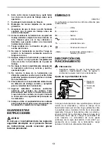
The followings show the symbols used for tool.
V
............................volts
A
...........................amperes
Hz
..........................hertz
....................alternating current
.......................no load speed
.......................Class II Construction
.../min
....................revolutions or reciprocation per
minute
FUNCTIONAL DESCRIPTION
CAUTION:
•
Always be sure that the tool is switched off and
unplugged before adjusting or checking function on
the tool.
Adjusting depth of cut
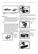
Place the tool on a flat surface. Loosen the clamp screw
and move the tool body until the bit just touches the flat
surface. Tighten the clamp screw slightly. Place the tool
on its side and loosen the clamp screw. Move the tool
base until the desired depth of cut is obtained. Depth of
cut can be checked with the scale label (1 mm (3/64”) per
graduation) on the tool. Then tighten the clamp screw
securely.
Switch action
CAUTION:
•
Before plugging in the tool, always be sure that the
tool is switched off.
•
Switch can be locked in “ON” position for ease of
operator comfort during extended use. Apply cau-
tion when locking tool in “ON” position and maintain
firm grasp on tool.
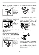
To start the tool, move the switch lever to the I (ON) posi-
tion. To stop the tool, move the switch lever to the O
(OFF) position.
ASSEMBLY
CAUTION:
•
Always be sure that the tool is switched off and
unplugged before carrying out any work on the tool.
Installing or removing trimmer bit
CAUTION:
•
Do not tighten the collet nut without inserting a bit,
or the collet cone will break.
•
Use only the wrenches provided with the tool.
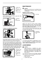
Insert the bit all the way into the collet cone and tighten
the collet nut securely with the two wrenches.
To remove the bit, follow the installation procedure in
reverse.
OPERATION
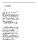
Set the tool base on the workpiece to be cut without the
bit making any contact. Then turn the tool on and wait
until the bit attains full speed. Move the tool forward over
the workpiece surface, keeping the tool base flush and
advancing smoothly until the cutting is complete.
When doing edge cutting, the workpiece surface should
be on the left side of the bit in the feed direction.
1. Scale label
2. Clamp screw
1. Switch lever
1
2
007107
1
007108
1. Loosen
2. Tighten
3. Hold
1
2
3
007106

