


A - 42
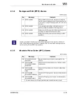
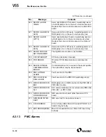
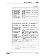
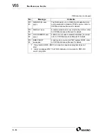
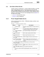
A.3.13
PMC Alarms
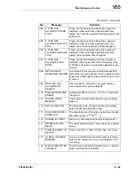
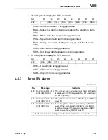
920
SERVO ALARM
(MAIN)
Servo alarm (Main CPU board). A watchdog alarm
or a RAM parity error in the servo module occurred.
Replace the servo control module on the Main CPU
board.
921
SERVO ALARM (3/4
AXIS)
Servo alarm (3rd or 4th axis). A watchdog alarm or a
RAM parity error in the servo module occurred.
922
SERVO ALARM
(OPT2)
Servo alarm (Option 2 board). A watchdog alarm or
a RAM parity error in the servo module occurred.
Replace the servo control module on the Option 2
board.
923
SERVO ALARM (7/8
AXIS)
Servo alarm (7th or 8th axis). A watchdog alarm or a
RAM parity error in the servo module occurred.
924
SERVO MODULE
SETTING ERROR
The digital servo module is not installed.
930
CPU INTERRUPT
CPU error (abnormal interrupt).
940
PCB ERROR
ID error of PCB. Main module or main board is
faulty.
945
SERIAL SPINDLE
COMMUNICATION
ERROR
Communications error occurred in the serial spindle.
The optical fiber may be disconnected.
950
PMC SYSTEM
ALARM
Fault occurred in the PMC.
951
PMC-RC WATCH
DOG ALARM
Fault occurred in the PMC-RC (watchdog alarm).
970
NMI OCCURRED IN
BOC
RAM parity error or NMI occurred in the PMC-RB or
PMC-RA2 module.
971
NMI OCCURRED IN
SLC
SLC communications error occurred in the PMC-RB,
PMC-RA1, or PMC -RA2.
972
NMI OCCURRED IN
OTHER MODULE
NMI occurred on a board other than main CPU
board.
973
NON MASK INTER-
RUPT
NMI occurred for an unknown reason.
974
F-BUS ERROR
Error in Fanuc BUS. Main CPU and OPTION 1 to 3
boards may be faulty.
975
BUS ERROR (MAIN)
Main CPU board BUS error. Main CPU board may
be faulty.
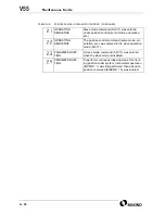
SYS Alarms (continued)
No.
Message
Contents
Summary of Contents for V55
Page 6: ...vi...
Page 32: ...1 24 NOTES SKETCHES...
Page 37: ...4V2A1563 E 2 3 FIGURE 2 1 SPINDLE POWER AND TORQUE CHARACTERISTICS...
Page 39: ...4V2A1563 E 2 5 FIGURE 2 2 AXIS CONFIGURATION TRAVEL AND WORK CUBE...
Page 41: ...4V2A1563 E 2 7 FIGURE 2 4 WORKPIECE SIZE LIMITATIONS...
Page 53: ...4V2A1563 E 2 19 FIGURE 2 6 FLOOR SPACE FOR STANDARD MACHINE...
Page 58: ...2 24 F IGURE 2 7 V55 WITH 25 TOOL ATC...
Page 59: ...4V2A1563 E 2 25 F IGURE 2 8 V55 WITH 25 TOOL ATC AND LIFT UP CHIP CONVEYOR LEFT...
Page 60: ...2 26 F IGURE 2 9 V55 WITH 25 TOOL ATC AND LIFT UP CHIP CONVEYOR RIGHT...
Page 61: ...4V2A1563 E 2 27 F IGURE 2 10 V55 WITH 25 TOOL ATC LIFT UP CHIP CONVEYOR LEFT AND APC...
Page 62: ...2 28 F IGURE 2 11 V55 WITH 25 TOOL ATC LIFT UP CHIP CONVEYOR RIGHT AND APC...
Page 63: ...4V2A1563 E 2 29 F IGURE 2 12 V55 WITH 40 OR 80 TOOL ATC...
Page 64: ...2 30 F IGURE 2 13 V55 WITH 40 OR 80 TOOL ATC AND LIFT UP CHIP CONVEYOR LEFT...
Page 65: ...4V2A1563 E 2 31 F IGURE 2 14 V55 WITH 40 OR 80 TOOL ATC AND LIFT UP CHIP CONVEYOR RIGHT...
Page 66: ...2 32 F IGURE 2 15 V55 WITH 40 OR 80 TOOL ATC LIFT UP CHIP CONVEYOR LEFT AND APC...
Page 67: ...4V2A1563 E 2 33 F IGURE 2 16 V55 WITH 40 OR 80 TOOL ATC LIFT UP CHIP CONVEYOR RIGHT AND APC...
Page 68: ...2 34 NOTES SKETCHES...
Page 93: ...4V2A1563 E 3 23 FIGURE 3 6 LEVELING BASE POSITIONS AND BED TO FLOOR CLEARANCE...
Page 94: ...3 24 NOTES SKETCHES...
Page 99: ...4V2A1563 E 4 3 FIGURE 4 1 MACHINE CORE ELEMENTS...
Page 103: ...4V2A1563 E 4 7 FIGURE 4 3 MAKINO PROFESSIONAL 3 CONTROL WITH MPC5...
Page 106: ...4 10 NOTES SKETCHES...
Page 114: ...4 18 NOTES SKETCHES...
Page 123: ...4V2A1563 E 5 5 FIGURE 5 1 BASIC TROUBLESHOOTING FLOW CHART...
Page 124: ...5 6 NOTES SKETCHES...
Page 143: ...4V2A1563 E 5 25 NOTES SKETCHES...
Page 153: ...4V2A1563 E 5 35 NOTES SKETCHES...
Page 159: ...4V2A1563 E 5 41 NOTES SKETCHES...
Page 166: ...5 48 NOTES SKETCHES...
Page 191: ...4V2A1563 E 5 73 TEC F IGURE 5 26 S CHEMATIC PAGE FORMAT...
Page 197: ...4V2A1563 E 5 79 NOTES SKETCHES...
Page 198: ...5 80 NOTES SKETCHES...
Page 202: ...NOTES SKETCHES...
Page 227: ...4V2A1563 E 6 25 NOTES SKETCHES...
Page 252: ...6 50 NOTES SKETCHES...
Page 261: ...4V2A1563 E 6 59 FIGURE 6 36 SPINDLE HYDRAULIC CIRCUIT...
Page 267: ...4V2A1563 E 6 65 FIGURE 6 40 L PORT SPINDLE LUBRICATION...
Page 269: ...4V2A1563 E 6 67 FIGURE 6 41 V PORT SPINDLE LUBRICATION...
Page 277: ...4V2A1563 E 6 75 NOTES SKETCHES...
Page 279: ...4V2A1563 E 6 77 FIGURE 6 48 SEALING ROD INSTALLATION...
Page 284: ...6 82 NOTES SKETCHES...
Page 293: ...4V2A1563 E 7 5 F IGURE 7 3 AXIS DRIVE CIRCUIT...
Page 297: ...4V2A1563 E 7 9 NOTES SKETCHES...
Page 309: ...4V2A1563 E 7 21 FIGURE 7 12 BALL SCREW COOLING OIL AND TAC BEARING LUBRICATION PIPING...
Page 311: ...4V2A1563 E 7 23 NOTES SKETCHES...
Page 317: ...4V2A1563 E 7 29 FIGURE 7 18 BALL SCREW PRE TENSION PROCEDURE...
Page 346: ...7 58 NOTES SKETCHES...
Page 348: ...7 60 FIGURE 7 35 Y AXIS COVER SYSTEM...
Page 351: ...4V2A1563 E 7 63 NOTES SKETCHES...
Page 369: ...4V2A1563 E 7 81 NOTES SKETCHES...
Page 370: ...7 82 NOTES SKETCHES...
Page 374: ...NOTES SKETCHES...
Page 386: ...8 12 NOTES SKETCHES...
Page 403: ...4V2A1563 E 8 29 NOTES SKETCHES...
Page 423: ...4V2A1563 E 8 49 NOTES SKETCHES...
Page 432: ...8 58 NOTES SKETCHES...
Page 439: ...4V2A1563 E 9 5 NOTES SKETCHES...
Page 441: ...4V2A1563 E 9 7 F IGURE 9 3 OIL CONTROLLER ELECTRICAL DRAWINGS...
Page 443: ...4V2A1563 E 9 9 FIGURE 9 4 OIL CONTROLLER MACHINE SYSTEM...
Page 464: ...9 30 NOTES SKETCHES...
Page 468: ...NOTES SKETCHES...
Page 490: ...A 22 NOTES SKETCHES...
Page 525: ...4V2A1563 E A 57 NOTES SKETCHES...
Page 526: ...A 58 NOTES SKETCHES...
Page 534: ...B 6 NOTES SKETCHES...
Page 546: ...B 18 NOTES SKETCHES...
Page 558: ...B 30 NOTES SKETCHES...
Page 564: ...B 36 NOTES SKETCHES...
Page 568: ...B 40 NOTES SKETCHES...


