


4V2A1563 (E)
8 - 51
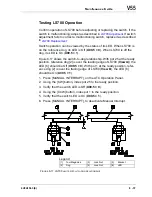
5. Manually load a tool holder into the spindle.
6. Select MDI and position Z axis to its 2
nd
reference position.
A. Key-in ’G30 G91 Z0’.
B. Press the [EOB] key.
C. Press the [INSERT] key.
D. Press Cycle [START].
7. Origin (set to zero) the relative coordinate display.
A. Press the [POS] function key.
B. Press the [REL] softkey.
C. Press the [ORIGIN] then [ALL EXEC].
8. Reference the tool magazine, using Maintenance mode.
A. Display the
MAINTENANCE MENU
screen -
B. Press [MODE SELECT] to activate Maintenance mode.
C. Press the [ATC MGZN] softkey.
D. Using the cursor keys, highlight
ZERO RETURN
.
E. Press the [SET] softkey
.
F. Press and hold the ATC Operation Panel [CW] button until the
magazine reaches its reference dog and aligns.
9. Display the
ATC MAINTENANCE
screen:
A. Press the [MENU PAGE] softkey.
B. Press the [ATC] softkey.
10. Open the ATC shutter.
A. Using the cursor keys, highlight
ATC SHUTER OPEN
.
B. Press the [ON] softkey.
11. Activate Stroke Extend mode.
A. Using the cursor keys, highlight
STROKE EXTEND
.
B. Press the [ON] softkey.
12. Select Handle mode and use the MPG to position X axis, close to the
magazine. Do not engage the gripper fingers in this step.
Summary of Contents for V55
Page 6: ...vi...
Page 32: ...1 24 NOTES SKETCHES...
Page 37: ...4V2A1563 E 2 3 FIGURE 2 1 SPINDLE POWER AND TORQUE CHARACTERISTICS...
Page 39: ...4V2A1563 E 2 5 FIGURE 2 2 AXIS CONFIGURATION TRAVEL AND WORK CUBE...
Page 41: ...4V2A1563 E 2 7 FIGURE 2 4 WORKPIECE SIZE LIMITATIONS...
Page 53: ...4V2A1563 E 2 19 FIGURE 2 6 FLOOR SPACE FOR STANDARD MACHINE...
Page 58: ...2 24 F IGURE 2 7 V55 WITH 25 TOOL ATC...
Page 59: ...4V2A1563 E 2 25 F IGURE 2 8 V55 WITH 25 TOOL ATC AND LIFT UP CHIP CONVEYOR LEFT...
Page 60: ...2 26 F IGURE 2 9 V55 WITH 25 TOOL ATC AND LIFT UP CHIP CONVEYOR RIGHT...
Page 61: ...4V2A1563 E 2 27 F IGURE 2 10 V55 WITH 25 TOOL ATC LIFT UP CHIP CONVEYOR LEFT AND APC...
Page 62: ...2 28 F IGURE 2 11 V55 WITH 25 TOOL ATC LIFT UP CHIP CONVEYOR RIGHT AND APC...
Page 63: ...4V2A1563 E 2 29 F IGURE 2 12 V55 WITH 40 OR 80 TOOL ATC...
Page 64: ...2 30 F IGURE 2 13 V55 WITH 40 OR 80 TOOL ATC AND LIFT UP CHIP CONVEYOR LEFT...
Page 65: ...4V2A1563 E 2 31 F IGURE 2 14 V55 WITH 40 OR 80 TOOL ATC AND LIFT UP CHIP CONVEYOR RIGHT...
Page 66: ...2 32 F IGURE 2 15 V55 WITH 40 OR 80 TOOL ATC LIFT UP CHIP CONVEYOR LEFT AND APC...
Page 67: ...4V2A1563 E 2 33 F IGURE 2 16 V55 WITH 40 OR 80 TOOL ATC LIFT UP CHIP CONVEYOR RIGHT AND APC...
Page 68: ...2 34 NOTES SKETCHES...
Page 93: ...4V2A1563 E 3 23 FIGURE 3 6 LEVELING BASE POSITIONS AND BED TO FLOOR CLEARANCE...
Page 94: ...3 24 NOTES SKETCHES...
Page 99: ...4V2A1563 E 4 3 FIGURE 4 1 MACHINE CORE ELEMENTS...
Page 103: ...4V2A1563 E 4 7 FIGURE 4 3 MAKINO PROFESSIONAL 3 CONTROL WITH MPC5...
Page 106: ...4 10 NOTES SKETCHES...
Page 114: ...4 18 NOTES SKETCHES...
Page 123: ...4V2A1563 E 5 5 FIGURE 5 1 BASIC TROUBLESHOOTING FLOW CHART...
Page 124: ...5 6 NOTES SKETCHES...
Page 143: ...4V2A1563 E 5 25 NOTES SKETCHES...
Page 153: ...4V2A1563 E 5 35 NOTES SKETCHES...
Page 159: ...4V2A1563 E 5 41 NOTES SKETCHES...
Page 166: ...5 48 NOTES SKETCHES...
Page 191: ...4V2A1563 E 5 73 TEC F IGURE 5 26 S CHEMATIC PAGE FORMAT...
Page 197: ...4V2A1563 E 5 79 NOTES SKETCHES...
Page 198: ...5 80 NOTES SKETCHES...
Page 202: ...NOTES SKETCHES...
Page 227: ...4V2A1563 E 6 25 NOTES SKETCHES...
Page 252: ...6 50 NOTES SKETCHES...
Page 261: ...4V2A1563 E 6 59 FIGURE 6 36 SPINDLE HYDRAULIC CIRCUIT...
Page 267: ...4V2A1563 E 6 65 FIGURE 6 40 L PORT SPINDLE LUBRICATION...
Page 269: ...4V2A1563 E 6 67 FIGURE 6 41 V PORT SPINDLE LUBRICATION...
Page 277: ...4V2A1563 E 6 75 NOTES SKETCHES...
Page 279: ...4V2A1563 E 6 77 FIGURE 6 48 SEALING ROD INSTALLATION...
Page 284: ...6 82 NOTES SKETCHES...
Page 293: ...4V2A1563 E 7 5 F IGURE 7 3 AXIS DRIVE CIRCUIT...
Page 297: ...4V2A1563 E 7 9 NOTES SKETCHES...
Page 309: ...4V2A1563 E 7 21 FIGURE 7 12 BALL SCREW COOLING OIL AND TAC BEARING LUBRICATION PIPING...
Page 311: ...4V2A1563 E 7 23 NOTES SKETCHES...
Page 317: ...4V2A1563 E 7 29 FIGURE 7 18 BALL SCREW PRE TENSION PROCEDURE...
Page 346: ...7 58 NOTES SKETCHES...
Page 348: ...7 60 FIGURE 7 35 Y AXIS COVER SYSTEM...
Page 351: ...4V2A1563 E 7 63 NOTES SKETCHES...
Page 369: ...4V2A1563 E 7 81 NOTES SKETCHES...
Page 370: ...7 82 NOTES SKETCHES...
Page 374: ...NOTES SKETCHES...
Page 386: ...8 12 NOTES SKETCHES...
Page 403: ...4V2A1563 E 8 29 NOTES SKETCHES...
Page 423: ...4V2A1563 E 8 49 NOTES SKETCHES...
Page 432: ...8 58 NOTES SKETCHES...
Page 439: ...4V2A1563 E 9 5 NOTES SKETCHES...
Page 441: ...4V2A1563 E 9 7 F IGURE 9 3 OIL CONTROLLER ELECTRICAL DRAWINGS...
Page 443: ...4V2A1563 E 9 9 FIGURE 9 4 OIL CONTROLLER MACHINE SYSTEM...
Page 464: ...9 30 NOTES SKETCHES...
Page 468: ...NOTES SKETCHES...
Page 490: ...A 22 NOTES SKETCHES...
Page 525: ...4V2A1563 E A 57 NOTES SKETCHES...
Page 526: ...A 58 NOTES SKETCHES...
Page 534: ...B 6 NOTES SKETCHES...
Page 546: ...B 18 NOTES SKETCHES...
Page 558: ...B 30 NOTES SKETCHES...
Page 564: ...B 36 NOTES SKETCHES...
Page 568: ...B 40 NOTES SKETCHES...


