

56, chemin de la Flambère · 31300 Toulouse · FRANCE · T é l . 3 3 ( 0 ) 5 6 1 3 1 8 6 8 7
F a x 3 3 ( 0 ) 5 6 1 3 1 8 7 7 3 · [email protected] · www.majorcom.fr
56, chemin de la Flambère · 31300 Toulouse · FRANCE · T é l . 3 3 ( 0 ) 5 6 1 3 1 8 6 8 7
F a x 3 3 ( 0 ) 5 6 1 3 1 8 7 7 3 · [email protected] · www.majorcom.fr
10
11
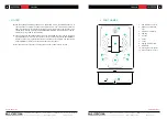
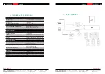
EMAGP16
EMAGP16
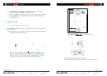
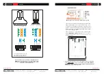
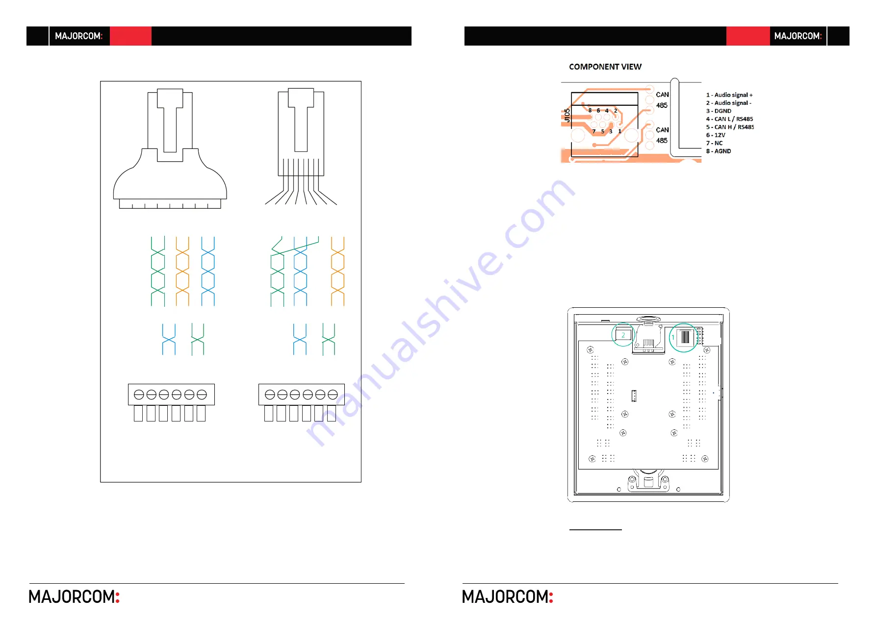
The remaining cable pair (N.C.) can be
used to double the +12V - GND pair, in
order to reach higher cable efficiency.
N.
C.
N.
C.
+
12V
G
N
D
O
UT
-
O
UT
+
C
A
N L
C
A
N H
N.
C.
N.
C.
+12V
C
A
N L
G
N
D
O
UT
-
O
UT
+
CA
N
L
CA
N
H
G
ND
+12V
CA
N
L
CA
N
H
G
ND
+12V
Usermanual V1.1
Usermanual V1.1
Both possibilities of connection between EMAGPE16and the
REMOTE ports in PXN matrices. Left- with the RJ45 to screw
terminals adapter / Right – without it, when no daisy-chained
units share the same REMOTE line
EMAGPE16RJ45 connector pinout diagram CAN bus mode
o
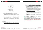
Connect as well the audio from the paging console micro
-
phone (Audio and - / OUT+ and -) to the + and –
terminals of one balanced audio input in the PXN matrix
(ground is common with CAN bus data ground). This will
be the input used in the PAGERS/DUCKERS module under
control by the paging station
o
Power connector
(2)
: if necessary, connect a backup power
supply (
WP24-PSU model
) (see section
5.2.2. Compati-
bility terms and external power supply requirements
for further details)
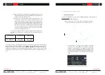
•
Check that both jumpers shown in the diagram below are positioned
in the
CAN position
. If the unit is
the last one in the CAN bus
wiring line, insert as well J111-J112 jumper, 120 ohm terminal
resistor ON
(closed contact
position)


