5
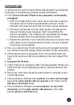
PROVING THE PHASE COMPARATORS
●
Before and after
using a Phase Comparator and accessories, a
functional test should be performed on the Phase Comparator as
it is to be used on the source or circuit to test.
●
A
High Voltage Insulation tester can be used
for this purpose.
●
When using a High Voltage Insulation tester, the Phase
Comparator will indicate the voltage generated by that H.V.
Insulation tester.
●
Please note that H.V. Insulation testers are generating DC voltage
and have polarity.
● The MT range of Phase Comparators are using a bridge rectifier
and current only passes one way into the panel meter. However,
the neon must illuminate both ways.
●
When proving with a DC source as with a H.V. Insulation tester,
the poles must be tested for both polarity to confirm that the panel
meter only show voltage in one way, but confirm that the neon
indicates both polarity.
●
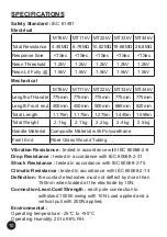
The reading on the High Voltage Insulation tester also indicates
the total value of the resistor chain and is also a good indication
that the circuit is still correct and in good condition (See
specifications).
●
A
Proving Unit
can also be used if a High Voltage Insulation
Meter is not available. The Proving unit does not indicate how
many mega ohms are in the front end or if the circuit is still in
good condition or not. The Proving unit will only output a DC
voltage of 5kVdc.
LIMIT MARK
●
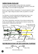
Each Phase Comparator has two poles.
●
Each pole has a front end which is in Fiberglass tubing.
●
Each pole has a Handle section.
●
At the junction between the handle section and the front end
section, there is a
RED BAND
which
is the limit mark
.
● By definition, this mark, or the
Red Band, indicates the physical
limit to which the poles of the Phase Comparators may be
inserted between live components or may touch them.

