background image

3

SAFETY RULES


Only Personnel who are fully 

trained

 in the use of High Voltage 

Phase Comparators should use this equipment.


Be aware that the system that it will be used on are powered from 

high voltages which are 

lethal

.


Before use, ensure that the Phase Comparators and any 

accessories are 

clean

, free from cracks or deep scores, and are 

properly secured together.


Only the proper rated Phase Comparators must be used. Ensure 

that the Phase Comparator is 

properly rated for the voltage

 of 

the system under test.


Test

 the operation of 

the Phase Comparator before and after


each test.


Do not allow any part of the Phase Comparator except the 

contact electrodes to come in contact with energized or earthed 

items.


Safe Working distance

 must always be observed.


Safety

 insulated 

Gloves and protective clothing

 and glasses 

must be when using the Phase comparator.


The Phase Comparator must be 

handled by one person only

.


Do 

not

 insert the Phase Comparator 

beyond its limit mark

 into 

the apparatus under test. 

The Limit mark is the red band

.


The Phase Comparator should 

not be used as a synchronizing


device or a voltage detector

.


The Interconnecting 

lead/cord must not

 be allowed to 

come


within

 100mm 

(10cm) of the

 hand guard and must not be 

touched while testing.


Before using the Phase Comparator in the testing of factory 

assembled switchgear, the 

manufacturer of the switchgear


must be consulted

 as the suitability of the Phase Comparator in 

such testing.


Always check for Phase Presence before testing between 

phases. Ensure that voltage is present on both phases 

before testing between phases.


The Phase Comparators are not to be subjected to a constant 

voltage for a period longer than 1 minute in every five minutes.

Summary of Contents for MT Series

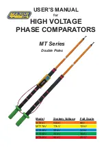
Page 1: ...USER S MANUAL for HIGH VOLTAGE PHASE COMPARATORS MT Series Double Poles Model System Voltage Full Scale MT6kV 6 6kV 8kV MT11kV 11kV 12kV MT22kV 22kV 24kV MT33kV 33kV 36kV MT44kV 44kV 48kV ...

Page 2: ...ATION PROVING THE PHASE COMPARATORS LIMIT MARK LABELS AND MARKING RANGE OF MODELS INSTRUCTION FOR USE OPERATION SPECIFICATIONS SCALES DIRECTIONS FOR USE TESTING FOR PHASING PRESENCE CARE AND MAINTENANCE LIMITED WARRANTY NOTES 3 4 4 5 5 6 7 8 9 10 11 12 13 14 15 16 ...

Page 3: ... Safety insulated Gloves and protective clothing and glasses must be when using the Phase comparator The Phase Comparator must be handled by one person only Do not insert the Phase Comparator beyond its limit mark into the apparatus under test The Limit mark is the red band The Phase Comparator should not be used as a synchronizing device or a voltage detector The Interconnecting lead cord must no...

Page 4: ...pole carries the panel meter with the colour coded scale and the integrated neon light indicator The colour coded scale indicates in phase out of phase band on the scale Green in phase Red out of phase The Neon light lights up when the voltage between the poles is greater than 1 2kV 1 5kV If two energized conductors are out of phase and a contact electrode is touched onto each pole current will fl...

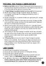
Page 5: ...ter only show voltage in one way but confirm that the neon indicates both polarity The reading on the High Voltage Insulation tester also indicates the total value of the resistor chain and is also a good indication that the circuit is still correct and in good condition See specifications A Proving Unit can also be used if a High Voltage Insulation Meter is not available The Proving unit does not...

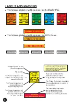
Page 6: ...AS PER INSTRUCTION MANUAL 44kV Voltage System for this Phase Comparator Part Number The Phase Comparator will operate over the frequency range 50 to 60 Hz The Phase Comparator is designed for use on High Voltage Systems The Phase Comparator will perform correctly over the temperature ranges of 25 C to 55 C Care must be taken to observe the attached labels which must not be removed The labels warn ...

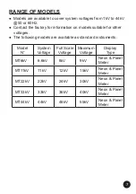
Page 7: ...ble for other voltages The following models are available as standard instruments Model N System Voltage Full Scale Voltage Maximum Voltage Display Type MT6kV 6 6kV 8kV 9kV Neon Panel Meter MT11kV 11kV 12kV 15kV Neon Panel Meter MT22kV 22kV 24kV 30kV Neon Panel Meter MT33kV 33kV 36kV 40kV Neon Panel Meter MT44kV 44kV 48kV 55kV Neon Panel Meter ...

Page 8: ...urn the test ON or the proving unit ON The Neon should light up if the voltage if high enough and the indicator should move nearest the voltage measured Reverse the poles of the Phase Comparator and check that an out of phase indication is given They are no user serviceable parts on our range of Phase Comparators Should the Phase Comparator become damaged faulty or suspect in any form please consu...

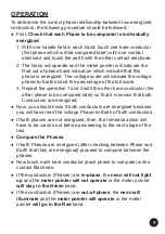
Page 9: ...tor the other phase to be compared later so that it is known that both Conductors are energized Now you should know if both conductors are energized because you will have read the voltage Phase to Earth of both conductors If both phases are not energized then the remedial action will have to be carried out before proceeding to the next stage of the test Compare the Phases If both Phases are energi...

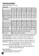
Page 10: ... 1kg 2 1kg 2 2kg 2 4kg 2 5kg Handle Material Composite Material with Polyurethane Front End Fiber Glass Wound Tubing Vibration Resistance tested in accordance with IEC 60068 2 6 Drop Resistance tested in accordance with IEC 60068 2 31 Shock Resistance tested in accordance with IEC 60068 2 75 Climatic Resistance tested in accordance with IEC 60068 2 14 Deflection the contact electrodes must not def...

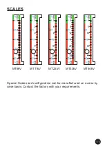
Page 11: ...11 SCALES MT6kV MT11kV MT22kV MT33kV MT44kV Special Scales and configuration can be manufactured on a case by case basis Contact the factory with your requirements ...

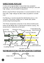
Page 12: ... the same voltage and in a stable state before commencing the phasing tests The Phase Comparators comprises of two interconnected parts these are the Master Stick containing the indicator housing The second stick is referred to as the slave REPRESENTATION FOR EXPLANATION PURPOSE Interconnecting Lead Master Stick Slave Stick M S S S Main Master Stick Protective Cover Slave Stick Hand Grip Insulatin...

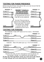
Page 13: ... Phases From different feeders Check that both phases to be compared are Live and have the same amplitude To check Phase presence measure the Voltage between Phase and Earth The result will confirm that voltage is present and that the amplitude are the same TESTING FOR PHASING No Indication Neon OFF does not illuminate IN PHASE Indication Neon ON does light up OUT OF PHASE Note that the links must...

Page 14: ...l Damage If surface scratches or dents can easily be seen by the naked eye then the equipment should be returned to the factory or your nearest distributor for repairs since these blemishes act as traps for dirt and moisture Mechanical damage would also necessitate the return of the equipment to the manufacturer Recalibration and Proof Testing Every twelve months the Phase Comparator and its acces...

Page 15: ...epaired or altered by unauthorized persons in any way so as in our sole judgement to injure their stability or reliability or which have been subject to misuse abuse misapplication negligence or accident or which have had the serial numbers altered defaced or removed All warranties implied by law are hereby limited to a period of twenty four months and the provisions of the warranty are expressly ...

Page 16: ... removed by the user For other kind of tips and contact electrodes contact the factory or your nearest distributor Getting regular training on your High Voltage equipment and on the electrical network grid you are working on is good practice and will help in keeping you safe Always make a sketch before proceeding with testing High Voltage and ensure you are fully in control of the testing and unde...

Reviews: