background image

Power on and Run Router


MP1900X Series Router Installation Manual


4-2 

copyright

2019 Maipu, all rights reserved


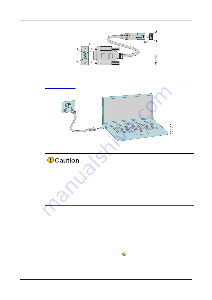
Figure 4-1 Console cable 

For details about the inner signal connection of the Console cables, refer to 

Appendix 

E1 Console Cable


Figure 4-2 Connect the router and PC via the Console port 


  When the PC (or laptop) is connected with the router via the configuration cable, 

first connect the DB-9 side of the configuration cable to the serial interface of the 
PC and then connect the RJ-45 connector of the configuration cable to the Console 
port of the router. 

  When removing the configuration cable that connects the PC (or laptop) with the 

router,  first  remove  the  RJ-45  connector  of  the  configuration  cable,  and  then 
remove the DB-9 side of the configuration cable. 


4.1.2

  Set PC HyperTerminal Parameters 

The following takes running Windows XP HyperTerminal on the PC (or laptop) as an 
example to describe the setting of the serial interface parameters of the PC (or laptop). 

Step 1:


Enable  the  PC  (or  laptop),  select 

Start

  > 

All  Programs

  > 

Accessories 

Communication 

HyperTerminal

, and click 

  to set up the new connection as shown 

in  Figure  4-5.  If  it  is  the  first  time  to  set  the  Hyperterminal,  the  system  displays  the 
interface of 

Location Information

, as shown in Figure 4-3. Fill in according to the red 

indication in the fiugre and click 

OK

Summary of Contents for MP1900X Series

Page 1: ...MP1900X Series Router Installation Manual V1 0...

Page 2: ......

Page 3: ...Communication Technologies Co Ltd shall under no circumstance be responsible for any accident negligence breach of contract defamation and infringement of copyright or intellectual property right inc...

Page 4: ...troubleshooting and equipment maintenance Product Version This manual is applicable to the product versions as below Product name Product Version MP1900X series router MP1900X 12 AC V1 MP1900X 22 AC V...

Page 5: ...e possible Convention of command formats Format Description Bold Keywords of command line Italic Parameters of command line Brace Options in the brace are compulsory Bracket Options in the bracket are...

Page 6: ...duction to the methods and steps of configuring the equipment software functions with the typical cases made available for reference Technical Support Technical support hotline 400 65710935 400 886 86...

Page 7: ...IRONMENT 2 1 2 2 SAFETY PRECAUTIONS 2 1 2 2 1 GENERAL SAFETY 2 1 2 2 2 ELECTRICAL SAFETY 2 2 2 2 3 STATIC SAFETY 2 2 2 2 4 LASER SAFETY 2 3 2 3 INSTALLATION TOOLS INSTRUMENTS AND EQUIPMENT 2 3 2 4 OPE...

Page 8: ...TEMPERATURE INFORMATION 4 14 4 3 4 VIEW FAN STATUS INFORMATION 4 14 4 3 5 VIEW SWAPPABLE OPTICAL MODULE INFORMATION 4 15 5 TROUBLESHOOTING 5 1 5 1 TROUBLESHOOTING OF CONFIGURATION SYSTEM 5 1 5 1 1 TR...

Page 9: ...rements C 5 C1 4 Anti Interference Requirement C 6 C1 5 Grounding Requirement C 6 C2 Requirements for Power Supply C 6 C2 1 AC Power Supply Requirement C 6 C2 2 Suggestions on fundamental AC power sup...

Page 10: ...Preface MP1900X Series Router Installation Manual viii copyright 2019 Maipu all rights reserved E1 Console Cables E 1 E2 GE Ethernet Interface Cable E 2 F Environmental Substance Statement E 2...

Page 11: ...C POWER CABLE 3 13 FIGURE 4 1 CONSOLE CABLE 4 2 FIGURE 4 2 CONNECT THE ROUTER AND PC VIA THE CONSOLE PORT 4 2 FIGURE 4 3 LOCATION INFORMATION INTERFACE 4 3 FIGURE 4 4 THE TELEPHONE AND MODEM INTERFACE...

Page 12: ...LL THE INTERFACE DAUGHTER CARD 6 2 FIGURE 6 3 INSTALL THE INTERFACE DAUGHTER CARD 6 2 FIGURE 6 4 FIX THE CAPTIVE SCREW 6 3 FIGURE 6 5 UNINSTALL THE SFP MODULE 6 3 FIGURE 6 6 INSTALL THE DUST CAP OF TH...

Page 13: ...Series Router Installation Manual Preface copyright 2019 Maipu all rights reserved xi Appendix Figure APPENDIX FIGURE D 1 DIAGRAM OF ROUTER EQUIPOTENTIAL CONNECTION D 7 APPENDIX FIGURE E 1 CONSOLE CA...

Page 14: ...TABLE A 1 POWER CONSUMPTION AND DIMENSION A 1 APPENDIX TABLE A 2 ROUTER WEIGHT A 1 APPENDIX TABLE B 1 10BASE T 100BASE TX 1000BASE T RJ45 B 1 APPENDIX TABLE B 2 1000BASE X SFP B 2 APPENDIX TABLE B 7...

Page 15: ...ht 2019 Maipu all rights reserved xiii APPENDIX TABLE E 1 CONNECTION RELATIONSHIP OF THE CONSOLE CABLE E 1 APPENDIX TABLE E 4 CONNECTION TABLE OF THE GE ETHERNET RJ45 INTERFACE CABLE E 2 APPENDIX TABL...

Page 16: ......

Page 17: ...ications of MP1900X series router 1 1 MP1900X 12 AC Appearance and Hardware Structure The dimension of MP1900X 12 AC is 340mm 260mm 44 2mm W x D x H The front appearance diagram of MP1900X 12 AC is sh...

Page 18: ...rance and Hardware Structure The dimension of MP1900X 22 AC is 340mm 260mm 44 2mm W x D x H The front appearance diagram of MP1900X 22 AC is shown in Figure 1 3 and the rear appearance diagram is show...

Page 19: ...front panel of MP1900X series router Interface Name Description Reset function button Press it for 3s and the system restarts and restores the factory setting USB One USB interface USB2 0 standard CO...

Page 20: ...ndicates that the system fan status is alarm USB Green on indicates that the USB device works properly off indicates that no USB device is installed or the USB device is removed flash indicates that t...

Page 21: ...on Avoid placing the device with left outlet adjacently above and below the router 1 5 Power Module of MP1900X Series Router The back panel of MP1900X series router provides one power input MP1900X 12...

Page 22: ......

Page 23: ...the router running Air conditioning and ventilation system can ensure the normal running temperature and humidity conditions of the router For details refer to Appendix C1 Appendix C1 Environment Req...

Page 24: ...ents of the router especially installing the components with the circuit board such as board we should wear anti static wrists When holding the circuit board please hold the edge of the circuit board...

Page 25: ...MP1900X series router with the optical interface avoid directly viewing the laser beam from the optical module inside Viewing the laser beam from the optical module inside directly may damage your ey...

Page 26: ...The package comprises the carton plastic bags protection EPE and other packaging materials The open package steps are as follows Step 1 View the carton label and confirm the router model in the carto...

Page 27: ...l grounding of the workbench There is 10cm heat dissipation space around the router Do not place heavy things on the router 3 1 2 Install Router to Cabinet This section describes how to install the MP...

Page 28: ...2U and three holes on the square hole bar is 1U as shown in Figure 3 1 Figure 3 1 The minimum slide height The following describes how to install a slide to the 19 inch standard cabinet The installati...

Page 29: ...ce Goods in kind prevail Install Floating Nut to Cabinet Before installing the chassis to the cabinet first install the floating nut on the upright square hole bar on the both sides in the front of th...

Page 30: ...hly until the hanging ear of the router is closely cling to the square hole bar in the front of the cabinet The slide tray bears the weight The router is installed to the 19 inch standard cabinet as s...

Page 31: ...ure that enough space is reserved around the router for heat dissipation 3 2 Ground the Router For the router and human security the router must be grounded well The resistance between the router chas...

Page 32: ...of the router to other grounding bar of the installation place Fire hose and lightning rod grounding of the building are not the proper grounding location the grounding cable of the router should be...

Page 33: ...SPD ensure the PE terminal is grounded Insert the AC power plug of the router into the socket of the power SPD surge protection connector bar When only the green indicator indicating the running powe...

Page 34: ...boards are normal Step 4 Bind the cables tidily using cable ties The port lightning protector is not provided with the router The user can purchase it as required The port lightning protector aims for...

Page 35: ...the power cable check and ensure that the power switch is OFF 3 4 2 Connect AC Power Cable Step 1 Insert the AC power cable into the socket of the router power Step 2 Insert the AC power cable to the...

Page 36: ...0X Series Router Installation Manual 3 14 copyright 2019 Maipu all rights reserved Check and ensure that the power cable is connected correctly Check and ensure that the interface daughter card is ins...

Page 37: ...laptop with RS 232 serial port or USB interface to configure the router To configure the router via the PC or laptop connect according to the following steps Step 1 Prepare one PC or laptop Confirm th...

Page 38: ...When removing the configuration cable that connects the PC or laptop with the router first remove the RJ 45 connector of the configuration cable and then remove the DB 9 side of the configuration cab...

Page 39: ...hts reserved 4 3 Figure 4 3 Location information interface Step 2 Display the following Telephone and Modem interface and click OK Figure 4 4 The Telephone and Modem interface Step 3 Display the follo...

Page 40: ...face Step 4 Display the following Connect to interface select the serial interface used by the connection in the Connect using and click OK Figure 4 6 Connect to interface Step 5 Display the following...

Page 41: ...rights reserved 4 5 Figure 4 7 com Properties interface Step 6 Display the following test HyperTerminal interface and click Properties Figure 4 8 test HyperTerminal interface Step 7 Display the follow...

Page 42: ...ss Enter at the blank place and the serial port displays the print information The setting of the HyperTerminal is complete Figure 4 10 test Hyperterminal interface after setting 4 1 3 Power on and St...

Page 43: ...the router After loading all cards check as follows to ensure that the later configuration work can be done normally After the router is powered on the ventilation system works and check whether ther...

Page 44: ...twisted pair to connect the network Connection steps Step 1 Insert one side of the Ethernet twisted pair to the Ethernet electrical interface of the router RJ 45 port Step 2 Insert the other side of t...

Page 45: ...ed to the TX wire of the peer router Step 1 Wear the anti static wrist and confirm that the anti static wrist is well contacted with the skin and well grounded Step 2 Pull out the dust plug on the opt...

Page 46: ...he fiber into the interface slot directly Please install after unplugging the fiber When installing the SFP module do not use the hands to touch the gold finger of the SFP module directly The TX wire...

Page 47: ...SFP module Step 4 Insert the prepared fibers to the ports of the optical module in order Figure 4 17 Connect the optical fiber Step 5 Connect the other side of the fiber to the peer router If the opti...

Page 48: ...to view the software and hardware version information of MP1900X series router including system serial number hardware general information hardware version CPLD version Monitor version software versio...

Page 49: ...e File Software mirror file name Compiled The compiling time of the software mirror file Note If the version changes subject to the actual display 4 3 2 View Power Status Information You can use the s...

Page 50: ...Command router show environment Display as follows Mpu CPU temperature is 59 C 4 3 4 View Fan Status Information You can use the show system fan command to view the information of the fan used on the...

Page 51: ...f the information displayed via show optical all Field Description Name The name of the port where the optical module is located VendorName The name of the manufacturer of the optical module LaserWave...

Page 52: ......

Page 53: ...router If no problem is found in the above checks there may be the following reasons 1 The serial port connected to the configuration cable is wrong the actual selected serial port is not consistent w...

Page 54: ...works normally Step 2 Check whether the air outlet and inlet of the chassis are blocked If yes clean the air outlet and inlet to ensure the air passage is smooth If the problem remains after all the p...

Page 55: ...r service staff to help you solve the problem 1 The arrival time of the router 2 The serial number of the chassis labeled on the chassis 3 Software version number it can be viewed via show version in...

Page 56: ......

Page 57: ...rd of MP1900X series router does not support hot swap Step 1 Power off the router Step 2 Use a Phillips screwdriver to loosen the captive screws of the interface daughter card Use two hands to hold th...

Page 58: ...e slowly and horizontally until the panel of the interface daughter card has a distance of about 1cm to the panel of the service card At this time you will feel obvious blocking use your hand to push...

Page 59: ...touch the gold finger part of the SFP module directly Do not directly stare at the fiber connection holes of the optical module when the fiber is pulled down but the optical module is not pulled out...

Page 60: ...dule Use the hands to hold the two sides of the SFP module and push it into the SFP slot horizontally until the SFP module closely contacts the slot you can feel that the shrapnel at the bottom and to...

Page 61: ...ppable interface daughter card and pigtail of the router The main board can only be maintained by opening the cover and therefore it is not included in the de dusting All de dusting must be operated b...

Page 62: ...e maintenance risks de dust the interface daughter card of the router in the period with small traffic volumes During the router operation due to the charged interface daughter card and cross ventilat...

Page 63: ...cleaning agent is thorough and can effectively remove the harmful particles attached on the surface of the interface daughter card This method is characterized with difficult operation and high cost...

Page 64: ...l and material for cleaning For the small power optical interface use the clean and dry anti static soft rush to remove the dust on the surface of the optical interface if the dedicated cleaning tool...

Page 65: ...MP1900X 12 AC 13W 340mm 260mm 44 2mm W D H MP1900X 22 AC 15W 340mm 260mm 44 2mm W D H Appendix Table A 2 Router weight Model Weight kg MP1900X 12 AC 2 54 MP1900X 22 AC 2 64 B Specifications of Genera...

Page 66: ...C1212 1003 B2 1000Base X SFP Optical Interface Attributes Appendix Table B 2 1000Base X SFP Attribute Description Interface standard IEEE 802 3ab Interface type SFP Work mode 1000Mbps full duplex Con...

Page 67: ...value 9600bps Supported services Connect the local terminal such as PC and run the terminal emulation program on the terminal B5 Micro USB Interface Attributes Appendix Table B 5 Micro USB interface a...

Page 68: ...internal components of the router from short circuit and being burned C1 2 Humidity Requirement To ensure that the router can work normally it is recommended to maintain certain humidity in the equipm...

Page 69: ...The requirement for the dust content and particle diameter in the equipment room is as shown in the following table Appendix Table C 3 Dust requirement for equipment room Max diameter m 0 5 1 3 5 Max...

Page 70: ...power radio transmitters radar transmitter and high frequency high current equipment take electromagnetic shielding methods when necessary C1 5 Grounding Requirement The well grounding system is the...

Page 71: ...esign of tall buildings GB50045 95 The low voltage distribution is done according to Specifications for the design of low voltage electric power distribution systems GB50045 95 C2 2 Suggestions on fun...

Page 72: ......

Page 73: ...king ground and protection ground including shielded grounding and distribution frame lightning protection and grounding share a group of ground body 2 Protection ground shall be done for the metal pa...

Page 74: ...nication Power The grounding specification of the communication power is as shown in the following table Appendix Table D 3 Grounding specifications for communication power S N Description 1 The AC po...

Page 75: ...be added to the corresponding interface of the router with the PGND cable of the signal lightning arrester as short as possible 3 The outer conductor of the coaxial cable and both sides of the shielde...

Page 76: ...ection line of the indoor signal and should not be led aerially outdoors The general requirements for the wiring of the indoor cables The cable installation is required to be routed by category avoidi...

Page 77: ...ed and bundled by indoor and outdoor drawn from the outlet holes of different chassis to the user terminal or cascading router Precautions for Using Fiber When using the fiber to connect the network r...

Page 78: ...r because of too much force Avoid pulling pressing and extruding the fiber The permitted maximum tensile force and crush force of the fiber are as shown in the following table Appendix Table D 6 Permi...

Page 79: ...r supply PE line and the installed metal structure should ensure the equipotential connection For the equipotential connection of the interconnected routers refer to the following figure After connect...

Page 80: ......

Page 81: ...cable The one side of the cable is the crimping RJ 45 crystal plug and the other side is a DB9 hole The view of the console cable is shown in the following figure Appendix figure E 1 Console cable Th...

Page 82: ...rectional receiving and transmitting difference cable pairs Appendix Table E 2 Connection table of the GE Ethernet RJ45 interface cable RJ 45 Signal Direction RJ 45 1 TD0 1 2 TD0 2 3 TD1 3 6 TD1 6 4 T...

Page 83: ...strictly complying with the using conditions in the environmental protection use period the environmental substances or elements contained in the product do not leak or mutate The environmental prote...

Reviews: