background image

 10

 11

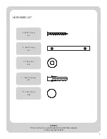
x 1

x 1

x 1

x 1

x 2

11

8

10

6

10

9

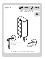
STEP   6

6 .   P a n   H e a d 

S c r e w

8 .   L o n g   F l a t 

H e a d   S c r e w 

9 .   Wa l l   S t r a p 

1 0 .   Wa s h e r

1 1 .   Wa l l

A n c h o r

position against wall

mark position of strap hole on wall

drill 1/4” hole

tap in wall anchor

fasten anti-tip strap with wall 

screw provided

 NOT TO SCALE. REFER TO PAGE 3 FOR ACTUAL SIZE HARDWARE.

Summary of Contents for MS18-D1-1007-14

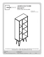
Page 1: ...77 436 7290 customersupport tenspringstreet com THIS INSTRUCTION BOOKLET CONTAINS IMPORTANT SAFETY INFORMATION PLEASE READ AND KEEP FOR FUTURE REFERENCE brown black Manufactured By BDDMI 1321 Tyler St...

Page 2: ...ON LEFT SHELF X2 RIGHT SHELF X3 A B C D E F G BACK PANEL LEG X4 H I Before you begin 1 Check for damaged or missing parts 2 Use the carton as a working surface to prevent product damage during assembl...

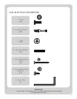
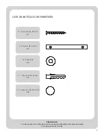
Page 3: ...AUTION 1 Make sure the screws go through the pre drilled holes properly 2 Do not over tighten bolts 5 Flat Head S crew x6 3 Cam x26 4 Wood D owel x16 1 B olt x16 2 Cam B olt x26 6 Pan Head S crew x19...

Page 4: ...4 10 Washer x2 HARDWARE LIST CAUTION 1 Make sure the screws go through the pre drilled holes properly 2 Do not over tighten bolts 8 Wall S crew x1 9 Wall Strap x1 11 Wall Anchor x1 12 Cam Cover x6...

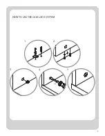
Page 5: ...5 1 2 3 4 5 180 HOW TO USE THE CAM LOCK SYSTEM...

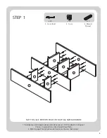
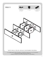
Page 6: ...ls into place Leave 1 2 of the dowels sticking out 2 Screw In cam bolts must be screwed down flush 3 Refer to page 4 for instructions on how to use the cam lock system 4 Wood D owel 2 Cam B olt 3 Cam...

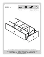
Page 7: ...into place Leave 1 2 of the dowels sticking out 2 Make sure the screws go through the pre drilled holes properly 3 Do not over tighten screws STEP 2 NOT TO SCALE REFER TO PAGE 3 FOR ACTUAL SIZE HARDW...

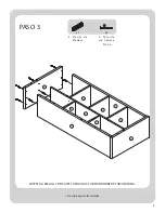
Page 8: ...8 x3 x6 4 Wood D owe l 5 Flat Head S crew 1 Do not over tighten screws STEP 3 NOT TO SCALE REFER TO PAGE 3 FOR ACTUAL SIZE HARDWARE...

Page 9: ...gin by installing all of the screws along one edge of the back panel Next using a square or tape measure make sure that the case is square if using a tape measure the distance from one corner diagonal...

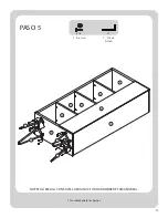
Page 10: ...10 x16 x1 1 Do not over tighten bolts STEP 5 1 B olt 7 Allen Wrench NOT TO SCALE REFER TO PAGE 3 FOR ACTUAL SIZE HARDWARE...

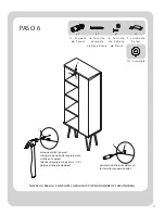
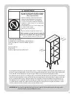
Page 11: ...w 8 Long Flat Head S crew 9 Wall Strap 10 Washer 11 Wall Anchor position against wall mark position of strap hole on wall drill 1 4 hole tap in wall anchor fasten anti tip strap with wall screw provid...

Page 12: ...and or abuse Please contact our Customer Service at 1 877 436 7290 to obtain information on warranty performance This warranty gives you specific legal rights and you may also have other rights which...

Page 13: ...290 customersupport tenspringstreet com ESTE MANUAL DE INSTRUCCIONES CONTIENE INFORMACI N IMPORTANTE DE SEGURIDAD POR FAVOR LEA Y GUARDE PARA REFERENCIA FUTURA marr n negro Fabricado Por BDDMI 1321 Ty...

Page 14: ...SA FIJA DERECHO X3 A B C D E F G PANEL POSTERIOR PATA X4 H I Antes de comenzar 1 Compruebe si hay piezas da adas o faltantes 2 Utilice la caja de cart n como superficie de trabajo para evitar da os al...

Page 15: ...los tornillos pasen por los agujeros pretaladrados de manera apropiada 2 No sobreapriete los tornillos 5 Tor nillo de Cabeza Plana x6 3 Leva x26 4 C lavija de M adera x16 6 Tor nillo de Cabeza de Nor...

Page 16: ...FERRETER A PRECAUCI N 1 Cerci rese que los tornillos pasen por los agujeros pretaladrados de manera apropiada 2 No sobreapriete los tornillos 8 Tor nillo de Pared x1 9 Cincha de Pared x1 11 Taquete de...

Page 17: ...5 1 2 3 4 5 180 COMO USAR EL SISTEMA FIJADOR DE LEVA...

Page 18: ...aliente de 1 27 cm en las clavijas 2 Los tornillos de leva deben de estar atornillados al ras 3 Refi rase a la p gina 4 para instrucciones para como usar el sistema de levas 4 Clavija de M adera 2 Tor...

Page 19: ...nte de 1 27 cm en las clavijas 2 Cerci rese que los tornillos pasen por los agujeros pretaladrados de manera apropiada 3 No sobreapriete los tornillos NO EST A ESCALA CONSULTE LA P GINA 3 FOR HARDWARE...

Page 20: ...8 x3 x6 4 Clavija de M adera 5 Tor nillo de Cabeza Plana PASO 3 1 No sobreapriete los tornillos NO EST A ESCALA CONSULTE LA P GINA 3 FOR HARDWARE DE TAMA O REAL...

Page 21: ...stalando todos los tornillos a lo largo de la orilla del panel posterior Despu s utilzando un cuadro o una cinta m trica aseg rese de que el gabinete est cuadrado si utiliza una cinta m trica la dista...

Page 22: ...10 x16 x1 PASO 5 1 Per no 7 Llave Allen 1 No sobreapriete los pernos NO EST A ESCALA CONSULTE LA P GINA 3 FOR HARDWARE DE TAMA O REAL...

Page 23: ...o Largo de Cabeza Plana 11 Taquete de Pared coloque contra la pared marque la posici n del agujero de la cincha en la pared taladre un agujero de 6 35 mm 1 4 golpee el taquete de pared apriete la cinc...

Page 24: ...cio al Cliente al 1 877 436 7290 para obtener informaci n sobre la garant a Esta garant a le otorga derechos legales espec ficos y usted tambi n puede tener otros derechos que var an de estado a estad...

Reviews: