background image

79

Mahr GmbH • Millimar C1202


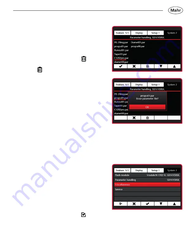
Deleting the parameter file

– Press 

 or 

 to select the 

parameter file to be deleted, or 

Ó

 to 

exit the submenu.

– 

Confirm selection by pressing 


– Press 

 to delete the parameter file 

or 

Ó

 to cancel the process.

6.2.3 Miscellaneous

– 

Select the 

Miscellaneous 

submenu 

using the 

 or 

 key.

– 

Select using 

4

 key or exit submenu 

using the 

Ó

 key.

– 

Make function active:


Use the 

 or 

 key to select the 

function and activate with the   key.

Summary of Contents for Millimar C 1202

Page 1: ... length measuring instrument 3723010 Mahr GmbH Carl Mahr Straße 1 D 37073 Göttingen Tel 49 551 7073 0 info mahr com www mahr com 0522 Millimar C 1202 Operating Instructions Valid from firmware version 1 0 0 1 ...

Page 2: ...symbol can cause inaccurate results and lead to equipment damage Introduction Permitted uses The Millimar C 1202 is an electronic length measuring and evaluation instrument for use in production Depending on the N 1700 module used e g two inductive or incremental measuring probes one or two pneumatic measuring instruments can be connected The operating maintenance and repair information detailed i...

Page 3: ...om your company safety officer 4 Before connecting up this measuring instrument please check the local mains supply voltage to ensure that it is within the working range of the AC adaptor 100 V 240 V 50 Hz 60 Hz If they do not match this measuring instrument must not be connected under any circumstances 5 The instrument may only be connected to a grounded power socket which complies with the regul...

Page 4: ...ility will be accepted for damages caused by other usage or as a result of the incorrect application of this measuring instrument Should your measuring task not be solved with this measuring instrument we can offer you another solution from our product range Please provide us with details of your measuring task Do not use an electric marking tool Disposal information Electronic equipment which was...

Page 5: ...6 2 Initial operation 17 2 1 Switching ON 17 2 2 Selecting the display language 17 2 3 Setting the measurement unit 17 2 4 Connecting the measuring probe 18 2 5 Selecting the probe type 18 2 6 Setting up the probe 20 2 7 Measuring screen 21 2 8 Switching OFF 21 3 Configuring the Feature menu 22 3 1 Select feature 22 3 2 Configuring the feature 22 3 2 1 Formula 22 3 2 1 1Factor 23 3 2 1 2 Function ...

Page 6: ... Display style 43 3 2 9 Display center at 45 4 Display menu 46 4 1 Brightness 46 4 2 Screensaver 46 5 Setup 47 5 1 Setup 1 47 5 1 1 Feature selection 47 5 1 2 Unit length 48 5 1 3 Unit angle 48 5 1 4 Master measurement mode 49 5 1 5 Number of masters 50 5 1 6 Master reset 50 5 2 Setup 2 51 5 2 1 Foot switch switching input 51 5 2 2 Sending data 53 5 2 3 Work mode 54 5 2 4 Measuring time 56 5 2 5 B...

Page 7: ...rection C2 68 6 1 2 3 Symmetry C1 to C2 69 6 1 3 Factory settings 72 6 1 4 Menu interlock 73 6 1 5 Info 75 6 1 6 Selecting the language 75 6 2 System 2 76 6 2 1 Updating module N 1700 76 6 2 2 Managing parameters 77 6 2 3 Miscellaneous 79 6 2 4 Service 80 7 Description of the interfaces 81 7 1 Compatible data cables 81 7 2 Data transmission parameters 82 8 Technical data 84 8 1 Compact length meas...

Page 8: ...8 Mahr GmbH Millimar C1202 1 3 2 4 1 Delivery and connection 1 1 Unpacking ...

Page 9: ...9 Mahr GmbH Millimar C1202 microSD B A 5 6 ...

Page 10: ...SD B A 1 2 Scope of delivery Slot for Micro SD memory card Scope of delivery Millimar C 1202 Power supply unit with interchangeable adapter Bus termination module Micro SD memory card Quick guide Bus termination module fitted in C 1202 ...

Page 11: ...331122 Millimar N 1702 U Module for 2 inductive probes 5331125 Millimar N 1702 M HR Module for 2 inductive probes 5331161 Millimar N 1702 Vss Module for 2 incremental probes 5331150 Millimar N 1701 PM 2500 Module for 1 pneumatic measuring instrument 5331151 Millimar N 1701 PM 5000 Module for 1 pneumatic measuring instrument 5331152 Millimar N 1701 PM 10000 Module for 1 pneum measuring instrument 5...

Page 12: ... sequential Hold down Toggle function Reset max min memory sequential Hold down Toggle function Set zero point parallel Hold down Toggle function Reset max min memory parallel Hold down Toggle function Data transfer disabled no con nection Data transfer Data transfer Manual disabled Data transfer manual Data transfer Sequential disabled Data transfer sequential Data transfer Parallel disabled Data...

Page 13: ...tion entry Cancel submenu entry Select item Deselect item Save settings to memory card Delete file from memory card Time controlled measuring mode Start measurement Pause measurement Stop measurement Reset max min memory Select feature Hold down Toggle function Select feature disabled Hold down Toggle function Start measurement Hold down Toggle function ...

Page 14: ...1 5 1 Display and operating keys Display Operating keys Scale Master measurement active Warning limit Measured value Tolerance limit Unit Measuring channel active Scale end value Angle in degrees Feature 1 Feature 2 Feature 3 Key function Hand for selecting a feature ...

Page 15: ...wo functions Pressing the key for longer than two seconds toggles the function Parallel mode Active function Second function Increase scale resolution Reduce scale resolution Hand select feature Start measurement in time controlled mode Master measurement Reset extreme value memory ...

Page 16: ... feature at which the hand is pointing Sequential mode Master measurement is performed for the feature at which the hand is pointing Hand switches automatically to next feature The master measurement can now be performed for this feature Parallel mode Master measurement is performed for all active features at the same time Slot for Micro SD memory card Measuring probe input C1 and C2 ...

Page 17: ...instrument and mains socket Press the ON OFF key The following appears on the display Start screen 2 3 Setting the measurement unit Select the relevant measuring unit with or Confirm entry by pressing key 4 2 2 Selecting the display language Select the relevant language with or Confirm entry by pressing key 4 ...

Page 18: ...uring probe Connect the measuring probe to probe input C1 2 5 Selecting the probe type Press the ON OFF key Menu appears Select Setup 3 with or and Select submenu Probe type C1 with or Select using 4 key or exit submenu using Ó key Probe input C1 and C2 ...

Page 19: ...oint before the first measurement To do this use the Absolute mode that indicates the raw value or absolute value of the probe Select the relevant measuring probe type using or See Technical Data in the operating instructions for compatible measuring probes Confirm entry by pressing 4 key or cancel with Ó key Exit submenu with Ó or exit the settings menu by pressing the key ...

Page 20: ...mode with Confirm entry with 4 key or exit submenu with Ó key One or two measuring channels will appear Depends on N 1700 module used The value displayed is the direct value from the measuring sensor Adjust measuring probe mechanically close to 0 The scaling can be adjusted with the or key Exit the settings menu by pressing the key ...

Page 21: ...n be set to master value with 0 key Master value 0 2 8 Switching OFF The measuring screen must be active to switch off the C1202 using the ON OFF key Press ON OFF key for at least 2 seconds The instrument switches off The full operating instructions can be downloaded at www mahr com products on the product page ...

Page 22: ...ure M1 M2 M3 you wish to configure Only the active features will appear on the measuring screen See Section 5 1 1 Setup 1 Feature selection 3 2 Configuring the feature 3 2 1 Formula Select the Formula submenu using the or key Select using 4 key or exit submenu using Ó key The formula editor appears Press the key to edit the formula Factor is selected ...

Page 23: ...e 4 key to confirm the value or Ó to exit the submenu Use to select Function or or Ó to finish editing the formula and to accept changes or Ó to exit the formula editor without applying the changes If a value is changed but the change has not yet been saved the Formula text appears in gray The changed formula can only be saved when the row with Formula appears in red ...

Page 24: ...Function submenu Use the or key to select the relevant function Use the 4 key to confirm the function or Ó to exit the submenu Use to select Connector or the or Ó key to finish editing Formula and to accept changes or Ó to exit the Formula Editor without applying the changes ...

Page 25: ...d or if the currently valid maximum value is exceeded This function is used to calculate the mean of the maximum value and the minimum value Average The average of all of the previously measured single values is always shown The average value is calculated using the following formula measuring value 1 measuring value 2 measuring value x Number x of single measuring values Max Min The difference be...

Page 26: ...ducer at measuring channel C1 C2 Raw value of transducer at measuring channel C2 C2 inverted raw value of transducer at measuring channel C2 C1 C2 Sum of transducer raw values at measuring channels C1 and C2 C1 C2 Difference of the raw values If C2 C1 the difference is positive if C2 C1 it is negative C2 C1 Difference of the raw values If C2 C1 the difference is positive if C2 C1 it is negative C1...

Page 27: ...Formula and to accept changes or Ó to exit the Formula Editor without applying the changes 3 2 1 4 Divisor Use the 4 key to select the Divisor submenu Use the key to select the digit and the or key to enter the relevant value Use the 4 key to confirm the value or Ó to exit the submenu ...

Page 28: ...or the or Ó key to finish editing Formula and to accept changes or Ó to exit the Formula Editor without applying the changes Use the key to switch to measuring mode or Ó to exit the Feature submenu or 4 to edit Formula or to scroll through the submenu ...

Page 29: ...aster measurement Only one master gage block is contacted in a one point master measurement and the displayed value is compared with the entered nominal value This determines if the actual value just measured deviates from the nominal value and if so by how much It is assumed that the deviation determined here is constant across the entire measuring range and corrects the raw values of the subsequ...

Page 30: ...o masters gage blocks of different sizes are contacted in sequence and the actual values displayed are compared with the nominal values indicated on the masters First as for the one point master measurement the deviation from the nominal value is calculated from the measurement on the first smaller gage block and then corrected The characteristic curve of the probe is thus shifted accordingly agai...

Page 31: ... the Ó key or and to select the Feature M1 M2 M3 you wish to configure Select the Master submenu using the or key Select using 4 key or exit submenu using Ó key Press the to edit the values for Min master and Max master Use the 4 key to select the Min master submenu ...

Page 32: ...the submenu Use to select Max master or the or Ó key to finish editing Master value and to accept changes or Ó to exit the Master Value Editor without applying the changes Use the 4 key to select the Max master submenu Use the key to select the digit and the or keys to enter the relevant value Use the 4 key to confirm the value or Ó to exit the submenu ...

Page 33: ...he change has not yet been saved the Master text appears in gray The changed master values can only be saved when the row with Master appears in red Use the key to switch to measuring mode or Ó to exit the Feature submenu or 4 to edit the master or to scroll through the submenu If a greater number is entered for Min master than for Max master the numbers will appear in yellow The entries cannot be...

Page 34: ... the Nominal value submenu using the or key Select using 4 key or exit submenu using Ó key Use the key to select the digit and the or keys to enter the relevant value Use the 4 key to confirm the value or Ó to exit the submenu Use the key to switch to measuring mode or Ó to exit the Feature submenu or 4 to edit the Nominal value or to scroll through the submenu ...

Page 35: ...and to select the Feature M1 M2 M3 you wish to configure Select the Tolerance submenu using the or key Select using 4 key or exit submenu using Ó key Press to activate the tolerance evaluation Press to edit the values for Lower value and Upper value Use the 4 key to select the Lower value submenu ...

Page 36: ...value than for the upper value the numbers will appear in yellow The entries cannot be saved Use the key to select the digit and the or keys to enter the relevant value Use the 4 key to confirm the value or Ó to exit the submenu Use to select Upper value or or Ó to finish editing the tolerance and to accept changes or Ó to exit the Tolerance Editor without saving the changes ...

Page 37: ...elect the Upper value submenu Use the key to select the digit and the or key to enter the relevant value Use the 4 key to confirm the value or Ó to exit the submenu Use to select Lower value or or Ó to finish editing Tolerance and to accept changes or Ó to exit the Tolerance Editor without applying the changes Use the key to switch to measuring mode or Ó to exit the Feature submenu or 4 to edit th...

Page 38: ... and to select the Feature M1 M2 M3 you wish to configure Select the Warning limits submenu using the or key Select using 4 key or exit submenu using the Ó key Press to activate the warning limits Press to edit the values for Lower value and Upper value Use the 4 key to select the Lower value submenu ...

Page 39: ...e numbers will appear in yellow The entries cannot be saved Use the key to select the digit and the or key to enter the relevant value Use the 4 key to confirm the value or Ó to exit the submenu Use to select Upper value or or Ó to finish editing Warning limits and to accept changes or Ó to exit the Warning limits Editor without applying the changes Use the 4 key to select the Upper value submenu ...

Page 40: ...the key to select the digit and the or key to enter the relevant value Use the 4 key to confirm the value or Ó to exit the submenu Use to select Lower value or or Ó to finish editing the Warning limits and to accept changes or Ó to exit the Warning limits Editor without applying the changes Use the key to switch to measuring mode or Ó to exit the Feature submenu or 4 to edit the Warning limits or ...

Page 41: ...ution angle for function atan Press the ON OFF key Menu appears Use the Ó key or and to select the Feature M1 M2 M3 you wish to configure 3 2 6 1 Resolution length Select the Resolution length submenu using the or key Select using 4 key or exit submenu using the Ó key Use the or key to select the relevant resolution Use the 4 key to confirm the selection or Ó to exit the submenu Use the key to swi...

Page 42: ...n Use the 4 key to confirm the selection or Ó to exit the submenu Use the key to switch to measuring mode 3 2 7 Name Press the ON OFF key Menu appears Use the Ó key or and to select the Feature M1 M2 M3 you wish to configure Select the Name submenu using the or key Select using 4 key or exit submenu using Ó key Use the or key to select the relevant letter A Z is possible Use the key to select Numb...

Page 43: ...tyle Press the ON OFF key Menu appears Use the Ó key or and to select the Feature M1 M2 M3 you wish to configure Select the Display style submenu using the or key Select using 4 key or exit submenu using the Ó key Use the or key to select the relevant display style Use the 4 key to confirm the selection or Ó to exit the submenu Use the key to switch to measuring mode ...

Page 44: ...argraph and Digital display style Reset max value Unit Measurement active Function max Measured value max Measured value max is within the tolerance background is green Warning limit Tolerance limit Scale end Measured value max Pointer current measured value Measured value max Measured value max is greater than the warning limit background is yellow Bar current measured value ...

Page 45: ... Select using 4 key or exit submenu using the Ó key With asymmetric tolerances the tolerance field might displayed outside the scaled analog display In this case it is advisable to center the display to the center of the tolerance rather than to the nominal size Use the or key to select the relevant centering Use the 4 key to confirm the selection or Ó to exit the submenu Use the key to switch to ...

Page 46: ... using the Ó key Use the or key to select the relevant brightness Use the 4 key to confirm the selection or Ó to exit the submenu 4 2 Screensaver Press the ON OFF key Menu appears Press Ó or to select Display Select the Screensaver submenu using the or key Use the 4 key to confirm the selection or the Ó key to exit the submenu Use the or key to select the relevant time before the screensaver activ...

Page 47: ... or and to select Setup 1 5 1 1 Feature selection Select the Feature selection submenu using the or key Select using 4 key or exit submenu using the Ó key Make feature active Use the or key to select the feature and activate with the key Make feature passive Use the or key to select the feature and deactivate with the key Use the 4 key to confirm the selection or the Ó key to exit the submenu ...

Page 48: ...levant unit Use the 4 key to confirm the selection or Ó to exit the submenu Use the key to switch to measuring mode 5 1 3 Unit angle Select the Unit angle submenu using the or key Select using 4 key or exit submenu using the Ó key Use the or key to select the relevant unit Use the 4 key to confirm the selection or Ó to exit the submenu Use the key to switch to measuring mode ...

Page 49: ...rement mode Manual Master measurement is performed for the feature at which the hand is pointing Sequential Master measurement is performed for the feature at which the hand is pointing Hand switches automatically to next feature Parallel Master measurement is performed for all active features at the same time Select using 4 key or exit submenu using the Ó key Use the key to switch to measuring mo...

Page 50: ...ction 3 2 2 Master Use the 4 key to confirm the selection or Ó to exit the submenu Use the key to switch to measuring mode 5 1 6 Master reset Select the Master reset submenu using the or key or exit the submenu using the Ó key or switch to measuring mode using the key Use the 4 key to delete the master values set in measuring mode C 1202 switches to measuring mode The values displayed now refer di...

Page 51: ... key Select using 4 key or exit submenu using the Ó key Make the switching input function active Use the or key to select the function and activate with the key You can only select functions that are available on the basis of the current settings The other functions are grayed out Make switching input function passive Use the or key to select the function and deactivate with the key ...

Page 52: ...eft Send data Start and Stop are active functions of the foot switch The first time you press the foot switch the measurement will start The second time you press the foot switch the measurement will stop and the measured value will be sent via the interface Use the 4 key to confirm the selection or Ó to exit the submenu Use the key to switch to measuring mode ...

Page 53: ...ting will be sent Sequential Measured value for the feature at which the hand is pointing will be sent Hand switches automatically to next feature Parallel The measured values for all the active features will be sent one after the other If only one feature is active only the measured value for the active feature will be sent regardless of the selected mode Use the 4 key to confirm the selection or...

Page 54: ...uring values The active features are calculated on the basis of the formula linking and function and the results are displayed Use the 0 key to delete the max min and average memory and start a new measurement If one of the settings Max Min 2 Max Min or Average was selected under Formula the calculated total or difference or the average is continuously updated The 0 key resets the current value A ...

Page 55: ...e key ends the measurement and displays the results The measurement recording then switches off The recording of measurements can be paused with the key pause and resumed with the key This is helpful e g for radial runout measurements with a discontinuous profile As long as a measuring routine is active a green bar is displayed in the center box Measurement started Ready to measure measurement val...

Page 56: ...ey Use the key to select the digit and the or key to enter the relevant value Use the 4 key to confirm the value or Ó to exit the submenu If a time other than 0 was set under Measuring time measurement stops automatically after this time A green bar appears in the center box at the bottom for the duration of the set measuring time The length of the bar indicates the lapsed time Measuring time acti...

Page 57: ...Use the 4 key to confirm the value or Ó to exit the submenu If a time other than 0 is entered under Break time a new measurement will begin automatically once the Break time has elapsed A green bar appears in the fourth box at the bottom for the set break time The length of the bar indicates the lapsed time The measurement and break sequence is paused by pressing the key and resumed with the or ke...

Page 58: ... to pass between the moment Start is pressed and the measurement starts you can enter a time period by which the start of the measurement is delayed A start delay is particularly useful when a dynamic measurement e g on a shaft is performed and it is supposed to start automatically via a switch contact on the measuring device When the shaft is approached vibrations occur in the measuring device th...

Page 59: ... C1202 Use Ó to select the main menu Use the key to switch to measuring mode A green bar appears in the second box at the bottom during the set start delay The length of the bar indicates the lapsed time Start delay active ...

Page 60: ...is factor Select the Factor C1 submenu using the or key Select using 4 key or exit submenu using the Ó key Use the key to select the digit and the or key to enter the relevant value Use the 4 key to confirm the value or Ó to exit the submenu 5 3 2 Factor C2 Set the channel factor Measured values from the sensor to channel 2 are multiplied by this factor Implement the settings as described under 5 ...

Page 61: ...N 1702 M module is being used the measuring signal from the sensor is multiplied by the following factor Standard Range x 1 Long Range x10 For compatible probes see Section 8 2 Select using 4 key or cancel using Ó key Exit submenu with Ó or exit the settings menu by pressing the key 5 3 4 Probe type C2 Select probe type for channel C2 Implement the settings as described under 5 3 3 Probe type C1 ...

Page 62: ...as a measured value Then the oldest value is deleted and a new value is added to calculate the new average and display it as a measured value Use the 4 key to confirm the selection or the Ókey to exit the submenu Use the key to switch to measuring mode The signals of the probes can be filtered in order to avoid disturbances caused by grooves or dirt on the workpiece The number of values for filter...

Page 63: ...he Absolute mode using the or key Select using 4 key or exit submenu using the Ó key One or two measuring channels will appear depending on the N 1700 module used The value displayed is the direct value from the measuring sensor Adjust measuring probe mechanically close to 0 The scaling can be adjusted with the or key Press the key to leave the settings menu ...

Page 64: ... using 4 key or exit submenu using the Ó key 6 1 2 1 1 Customer calibration activation If a customer calibration is already available it can be activated by selecting this menu item Select Customer calibration activation using the or key Select using 4 key or exit submenu using the Ó key The active correction for the measuring channel is displayed under Calibration in the menu C1 Customer calibrat...

Page 65: ...s electrical zero point should be set on a 1 000 mm gage block for a customer calibration like the one in this example where a 2 000 mm gage block is used for the MAX value and the measuring plate represents the MIN value 6 1 2 1 2 Performing customer calibration Select the Calibration submenu using the or key Select using 4 Select the Calibration C1 submenu using the or key Select using 4 Select ...

Page 66: ...libration max and enter the relevant value as explained above To execute the customer calibration use the key to select Perform customer calibration Use the 4 key to confirm the value or Ó to exit the submenu The display shows information on how to position the probe Use the 4 key to confirm the value or Ó to cancel the process Progress of the measurement is indicated by a green progress bar ...

Page 67: ...tion or Ó to cancel the process An error message appears if the measured values of the customer calibration are not plausible Use 4 to repeat the customer calibration or Ó to cancel the process To avoid any measurement errors that may be caused by a previously created customer calibration it is advisable to activate the factory standard calibration again This is always stored in the measuring inst...

Page 68: ...tion using the or key The active correction for the measuring channel is displayed under Calibration in the menu C1 Customer calibration C2 Factory calibration 6 1 2 2 Calibration C2 Select the Calibration submenu using the or key Select using 4 key or exit submenu using the Ó key Select the Calibration C2 submenu using the or key Settings and corrections can now be performed for channel C2 as des...

Page 69: ...rfect electrical zero point in our example where a 2 000 mm gage block is used for the MAX value and the measuring plate represents the MIN value 6 1 2 3 Symmetry C1 to C2 When balancing two probes a customer calibration is performed on the two probes at both measuring channels in succession Select the Calibration submenu using the or key Select using 4 Select the Symmetry C1 to C2 submenu using t...

Page 70: ...ration max and enter the relevant value as explained above To balance use the key to select Perform customer calibration Use the 4 key to confirm the value or Ó to exit the submenu The display shows information on how to position the probe at C1 Use the 4 key to confirm or Ó to cancel the process Progress of the measurement is indicated by a green progress bar ...

Page 71: ...ss Then go through the same process for the probe at C2 Use the 4 key to confirm or Ó to cancel the process Following successful measurement press 4 to activate the customer calibration or Ó to cancel the process An error message appears if the measured values of the customer calibration are not plausible Use 4 to repeat the customer calibration or Ó to cancel the process ...

Page 72: ...y Select action with or key No cancel Yes instrument is reset to factory settings Select using 4 key or exit submenu using the Ó key Progress is indicated by a green progress bar At the end of the process the C1202 restarts The start screen appears briefly The language and unit of measurement need to be selected See also initial commissioning Section 2 ...

Page 73: ...n with or key Off switch off lock On switch on lock with PIN already entered To activate the lock the PIN must not be 0000 Select using 4 key or exit submenu using the Ó key Press the key to edit the PIN Use the key to select the position and the or keys to enter the relevant value Use the 4 key to confirm the value and activate the lock or Ó to exit the submenu ...

Page 74: ...he menu The menu will open once the PIN has been entered correctly The menu lock remains deactivated for another minute after exiting the menu This means that the PIN does not have to be re entered every time you exit the menu for adjustments If you have forgotten the PIN you can request the master PIN from Mahr GmbH ...

Page 75: ...ly in use Name article number serial number and firmware version Press Ó to exit the info display Use the key to switch to measuring mode 6 1 6 Selecting the language Select the Language submenu using the or key Select using 4 key or exit submenu using the Ó key Select the relevant language with the or keys Use the 4 key to confirm the selection or Ó to exit the submenu Use the key to switch to me...

Page 76: ... inserted into the C 1202 Select the Flash module submenu using the or key Select using 4 key or exit submenu using the Ó key Use or to select the firmware file for the N 1700 module in use or exit the submenu using the Ó key Please check that the right firmware file is saved on the Micro SD card If the wrong firmware is sent to the N 1700 module it will stop working and will have to be sent to Ma...

Page 77: ... progress bar Following successful update of the N 1700 module open the menu with the 4 key If the update was not successful an error message appears 6 2 2 Managing parameters A Micro SD card must be inserted in the C 1202 to save or load setting parameters Select the Parameter handling submenu using the or key Select using 4 key or exit submenu using the Ó key ...

Page 78: ...nd the or key to enter the relevant characters Any six characters can be assigned as the name A consecutive 2 digit number is added automatically Possible characters a z 0 9 _ Press 4 to save parameters or Ó to cancel the entries Loading parameters Press or to select the parameter file or Ó to exit the submenu Confirm selection by pressing key 4 Press 4 to load the parameter file or Ó to cancel th...

Page 79: ...o exit the submenu Confirm selection by pressing Press to delete the parameter file or Ó to cancel the process 6 2 3 Miscellaneous Select the Miscellaneous submenu using the or key Select using 4 key or exit submenu using the Ó key Make function active Use the or key to select the function and activate with the key ...

Page 80: ...ong press If this function is activated you can save a copy of the current screen to the Micro SD card by holding down key 5 A Micro SD card must be inserted in the C 1202 for this 6 2 4 Service This is a menu item for Mahr Service The submenu can only be opened with the Service password Make function passive Use the or key to select the function and deactivate with the key Use the 4 key to confir...

Page 81: ...interfaces 7 1 Compatible data cables USB data cable DK U1 Order no 4102603 Transmission parameters Transmission speed 9600 baud 1 start bit 7 ASCII bits even parity 2 stop bits Further information can be found in the data cable operating instructions ...

Page 82: ...02 and the N 1700 module in use VER For modules with 2 measuring channels 1_VER_X Y Z R_2_VER_X Y Z _3_VER_X Y Z For modules with 1 measuring channel 1_VER_X Y Z R_2_VER_X Y Z 1 Basic device C1202 2 Measuring channel C1 3 Measuring channel C2 depends on connected modules VER_X Y Z R X hardware option Y main function option Z new option feature R fix or change existing options Switch instrument off...

Page 83: ...eturns all the available tolerance limits separated by according to the sequence selected in Setup1 Feature selection Set warning limits TOLW1_ lowerTol _ higherTol _unit TOLW2_ lowerTol _ higherTol _unit TOLW3_ lowerTol _ higherTol _unit lowerTol higherTol decimal number maximum number of places depends on active unit mm XXX XXXX inch 3X XXXXXX deg 3XX XXXXX Every decimal number must contain a TO...

Page 84: ...f analog display Measuring range µm 5000 2000 1000 300 100 30 10 3 Measuring range mm 5 2 1 0 3 0 1 0 03 0 01 0 003 Measuring range inch 0 19 0 07 0 03 0 01 0 003 0 001 0 0004 0 0001 Dial graduation µm 500 200 100 20 10 2 1 0 2 Measuring range degrees 100 30 10 3 1 0 3 0 1 0 03 Measuring range Rad 1 5 0 5 0 1 0 05 0 01 0 005 0 001 0 0003 Measuring range Degrees Min Sec 100 30 10 3 60 18 6 1 Scale ...

Page 85: ...of displayed probe value The larger value applies Error limit scale display 0 25 of scale end value 0 3 of displayed value The larger value applies Data interface USB hardware interface USB control input RS485 Micro SD slot Power supply Mains powered 100 240 Volt 12V 1 5 A IP protection class 42 Weight excluding module 778 G Operating temperature range 0 C 40 C Storage temperature range 10 C 50 C ...

Page 86: ...004MA 5323020 P2004MB 5323030 P2104MA 5324070 P2104MB 5324080 Long range Carrier frequency 19 4 kHz Sensitivity 19 2 mV V mm Amplitude 5 Veff Type Order no P2010M 5324010 P2010MA 5324020 P2010MB 5324030 C1202 N 1702 T 5312025 5331121 TESA compatibility Standard range Carrier frequency 13 kHz Sensitivity 73 75 mV V mm Amplitude 3 Veff Type Order no P1300TA 4400190 P1300TB 4400191 P2004T 5323011 P20...

Page 87: ...ange Carrier frequency 7 5 kHz Sensitivity 115 mV V mm Amplitude 3 5 Veff Type Order no P2004U 5323013 P2004UA 5323023 P2004UB 5323033 P2104UA 5324073 P2104UB 5324083 Long range Carrier frequency 7 5 kHz Sensitivity 11 5 mV V mm Amplitude 3 5 Veff Type Order no P2010UA 5324023 P2010UB 5324033 ...

Page 88: ... 1 pneum measuring instrument 5331152 Millimar N 1701 PM 10000 Module for 1 pneum measuring instrument 5331155 Millimar N 1701 PF 2500 5000 Module for 1 pneum measuring instrument 5331156 Millimar N 1702 PF 2500 5000 4J Module for 1 pneum measuring instrument 5331157 Millimar N 1701 PF 10000 Module for 1 pneum measuring instrument from firmware C 1202 version 1 1 0 0 9 2 Other accessories 4102603 ...

Reviews: