MAHINDRA APPLITRAC
MAHINDRA
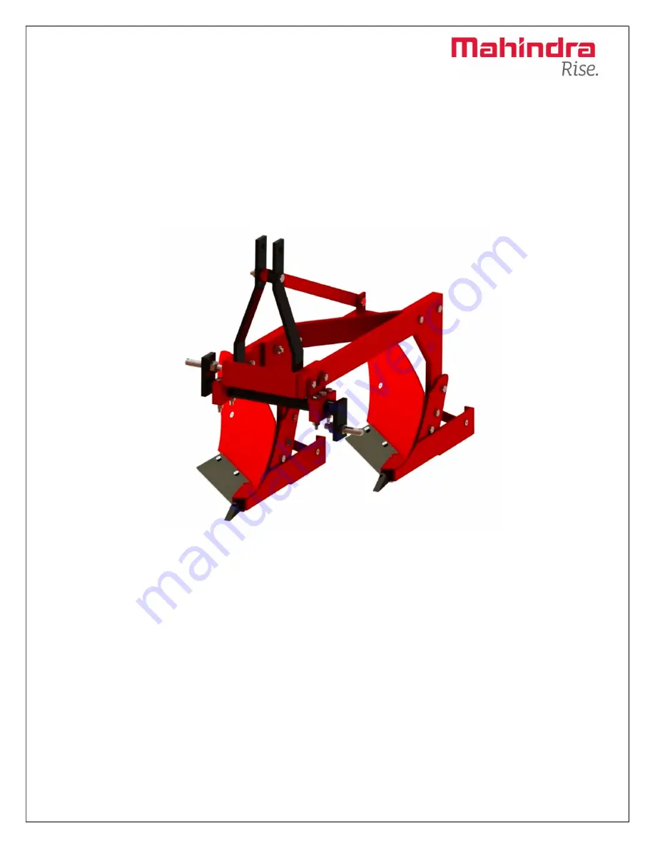
MB Plough
Part Catalogue
-Cum-
Service Manual
Mahindra & Mahindra Ltd, Farm Equipment Sector, AppliTrac
Department SAS Nagar, Mohali (Punjab) 140307. India
Page 1: ...MAHINDRA APPLITRAC MAHINDRA MB Plough Part Catalogue Cum Service Manual Mahindra Mahindra Ltd Farm Equipment Sector AppliTrac Department SAS Nagar Mohali Punjab 140307 India ...
Page 2: ...ication section opener maintenance in the Service section etc A detailed Table of Contents is found immediately behind this page and an Index is provided at the back of the manual Thanks again for purchasing this machine Customer Responsibility It is the Customer or Operator s responsibility to read the Operator s Manual to operate lubricate maintain and store the product in accordance with all in...
Page 3: ...r and to wait for the machine to stop moving Completely before repairing or adjusting the machine You risk the possibility of getting hands or clothing caught in or on the PTO or in a moving disk belt or chain while attempting to work on a machine while it is running Likewise bystanders or others working on the machine can get entangled in it Failing to block raised implement when working on them ...
Page 4: ...weights are required to offset the plough weight When the transporting on a road or highway always display SMV emblem and use lights and reflectors as required by state and local regulations Semi integral plough are quite long and caution must be used when turning to prevent swinging the plough in to fences or irrigation ditches Reduce speed when transporting over rough ground and avoid quick shar...
Page 5: ...it should be topped up Air cleaner should be checked to see whether it is clean or blocked If blocked it should be cleaned 2 3 Tyres The air pressure must be identical particularly on the rear tyres under difficult conditions addition wheel weight should be used or the tyres topped up evenly with water See operating instruction of the tractor manufacturer 2 4 Fan Belt and Important Nut Bolts Fan b...
Page 6: ...to one side implement works with different widths on the right and left this may cause by the side struts not having been released The function of the locking device of the automatic side should be checked and readjusted if necessary See the operating manual provided by the tractor manufacturer 2 8 Hydraulic For work the tractor hydraulic must be set to draft or mixed control See manufacturer inst...
Page 7: ...emoving ignition key Before starting plowing select one of the tillage patterns and follow the same to get the field leveled Operating the hydraulic controls I Position Control PC Lever Position control lever A controls the lifting and lowering of implement Make sure that all the discs of the plow are touching the ground and parallel to ground surface This will help in getting uniform depth of plo...
Page 8: ...its uppermost position Adjustments for MB Plough Adjusting the Width of Cut This adjustment should be used for increasing or decreasing the width of cut If the tractor is working under high load condition decrease the width of cut 1 Loosen the bolt A and four bolts of Bolt 2 on either side B 2 Rotate the hinge bar C so that the bolt A should fix to the next screw seat on the shaft 3 For decreasing...
Page 9: ...the tractor hydraulic system However more depth can be obtained by a Adding extra weight to the plough b Reducing the tilt angle A correctly tilted plough tends to penetrate better c If the ground is covered with trash set the Plough in almost vertical position and add weight to the plough In such soils notched Plough gives better results ...
Page 10: ...hten all nuts and bolts 4 Constantly check for loose nuts and bolts 5 Sharpen the Bar Point and Blades if the blades are dull Blunt blades increase the draft considerably Sr No Description 300HRS and above 100 HRS and less than 300HRS Reason 1 Nut Bolt Check proper tighten To avoid damages 2 Gunnel Bolt Check proper tighten To avoid damages of implement 3 3 Point Linkage Check proper tighten To av...
Page 11: ...MAHINDRA APPLITRAC 2 Lubrication and Maintenance Torque chart ...
Page 12: ...MAHINDRA APPLITRAC 3 ...
Page 13: ...MAHINDRA APPLITRAC 4 Assembly ...
Page 14: ...MAHINDRA APPLITRAC 5 Final Assembly ...
Page 15: ...ion happened during working in field Daily all bolt are properly inspected properly tight according to suitable torque 2 Top link setting Improper working in field operation Set properly according to operator manual 3 Draft control Uneven draft during field operation Used suitable Hp tractor for operation during taking turn always lift implement Proper use of Tractor DC Lever PC lever ...
Page 16: ...SS SHAFT MBPL0009 1 10 CROSS SHAFT BRACKET LOWER MBPL0010 4 11 CONNECTING FLAT MBPL0011 1 12 SHEAR PLATE MPPL0012 2 13 ROUND BUSH MBPL0013 2 14 CROSS SHAFT BRACKET UPPER MBPL0014 2 15 TILLER PIN TILPIN02 2 16 BOLT 5 8 X 3 HBSW583 2 17 BOLT 5 8 X 2 5 HBSW5825 6 18 BOLT 5 8 X 2 HBSW582 3 19 FALA BOLT 7 16 X 1 5 HBSW71615 12 20 BOLT 1 2 X 2 HBSW122 1 21 BOLT 1 2 X 4 HBSW124 4 22 BOLT 5 8 X 4 HBSW584 ...