46
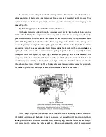
depth is reached, adjust the clearance between lowering stop block (3) and stop pin (4). After
adjustment, fix stop block (3) on return push rod (5) with bolt and nut, then raise the
implement several times to check the adjustment.
If the implement is provided with a supporting wheel, the floating control needs to be
used. Meanwhile, adjust lowering stop block (3) to the position where control lever1 (1) of
distributor (valve) will not return to neutral position.
③
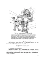
Adjustment of lowering speed
During adjustment, the lowering speed of the implement can be adjusted through
rotating the adjusting valve bolt (5) (see Fig.4-18). When the lowering speed is suitably
adjusted, use check screw (4) to limit the moving range of adjusting valve bolt.
④
Adjustment of safety valve
Safety valve has been adjusted before leaving the factory. In general, dismounting in
operation is not permitted anyhow. If the readjustment is necessary, it should be done on
special pressure test stand. The oil for test is HC-8(SY1152-77), the oil temperature should be
±
℃
controlled as 65
5
. When the press screw plug of safety valve is rotated clockwise, the
higher opening pressure is got, or vise versa.
In hydraulic system, as the precision of many parts is high, and the assembly parts have
been carefully tested and adjusted, cleanliness of the hydraulic oil, cleaning oil and the
environment should be especially paid attention to during operation, maintenance and fixing
the breakdowns. Generally free dismount is not allowed.
Notes: Before starting the engine, make sure there is enough oil in the lifter housing, so
as to avoid damage to the hydraulic gear pump.
10. Use and adjustment of air brake device of trailer
Summary of Contents for JINMA-200
Page 14: ...9 Fig 2 1 Controls and Instruments ...
Page 41: ...36 ...
Page 47: ...42 ...
Page 66: ...61 3 Distribution diagram of rolling bearing and transmission system of Jm series tractors ...
Page 67: ...62 ...
Page 71: ...66 ...

