


39
the steering gear, which has been decided during designing; if the radial or axial clearance of
the stator and rotor pair is too big to cause no manpower steering, then the rotor and stator
pair should be replaced. In other conditions, adjustment is not needed.
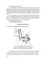
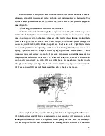
9. Construction and adjustment of hydraulic hitch system
Hydraulic hitch system consists of hydraulic system and hitch device. Hydraulic system
is an open circulating circuit system controlled by pressure circuit. The hitch device is rear-
attached 3 point hitch. Hydraulic system mainly consists of semi-separation attachment type
hydraulic lifter, gear pump, oil filter and their oil pipes (which connect them together).
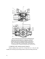
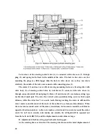
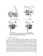
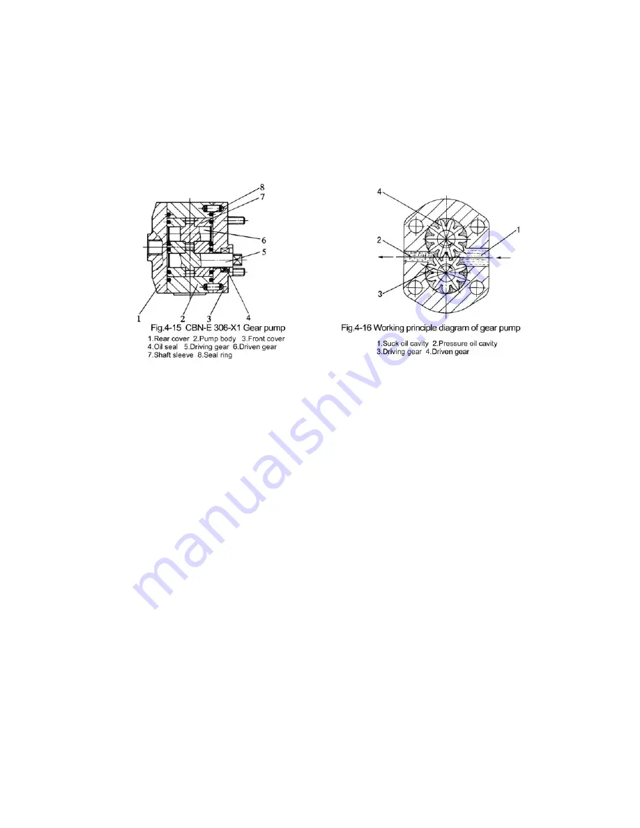
1) Working principle of gear pump
The gear pumps attached to Agracat series tractors are CBN model volume type outside
mesh gear pumps (Fig.4-15). They are all left handed pumps except the right handed pumps
on Agracat-160, 164 tractors. The gear pumps are mounted on the back end face of the right
side of the gear case of the diesel engine front, which are driven by engines. The gear pump is
made up of a pair of outside mesh shaft gear (5) and (6), gear body (2), sleeve (7) and rear
cover (1) and front cover (3).
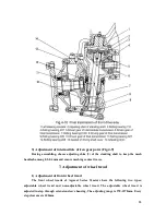
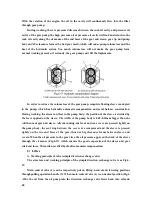
The working principle of the gear pump is as Fig.4-16. Take left-handed gear pump as
example: After starting the engine, the driving gear of gear pump rotates counterclockwise,
and the oil enters the teeth from the pressure oil cavity and fill the teeth with oil. The oil
entered the pump is surrounded and contained by sleeve, meshed teeth and pump body and
two oil cavities which are not connected with each other are formed: suck oil cavity and
pressure oil cavity. The gear rotates right cavity (suck oil cavity) and the inner gear teeth
return mesh to make the volume between gear teeth increase and form part vaccum, and the
oil in the tank is sucked in. Meanwhile the inner gear teeth of left cavity (pressure oil cavity)
begin to mesh (teeth into each other) to squeeze the oil among the teeth out of the oil pump.
Summary of Contents for JINMA-200
Page 14: ...9 Fig 2 1 Controls and Instruments ...
Page 41: ...36 ...
Page 47: ...42 ...
Page 66: ...61 3 Distribution diagram of rolling bearing and transmission system of Jm series tractors ...
Page 67: ...62 ...
Page 71: ...66 ...


