


41
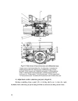
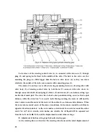
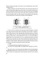
through returning oil cavity A according to the flow direction designated by the arrow of the
Fig4-19(b). Then the entering oil cavity B and returning oil cavity C of the cylinder are sealed
by main control valve (1); the oil cylinder is on seal and lock condition, and the implements
are maintained in the fixed position.
When the main control valve (1) is pushed to the lowering position (Fig.4-19d) from
neutral position, the returning oil cavity C is opened, the oil in the cylinder is squeezed back
into oil tank via returning oil cavity C under the action of the weight of the implement
according to the flow direction designated by the arrow in the Fig.4-19d, then the implement
is lowering. In such case the oil from oil pump into direction exchange valve still flows back
into oil tank through returning oil cavity A.
When the main control valve is pushed to lifting position from neutral position (Fig.4-
19c), the returning oil cavity A closes, while entering oil cavity B opens. Then the oil from oil
from oil pump into direction exchange valve enters the oil cylinder via oil cavity B according
to the flow direction designated by the arrow in Fig.4-19c, and push the piston forward, then
the implement begins to rise.
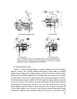
System safety valve is added and established in the direction exchange valve in order to
prevent the hydraulic components from being damaged due to overload during the rising of
the implement.
Summary of Contents for JINMA-200
Page 14: ...9 Fig 2 1 Controls and Instruments ...
Page 41: ...36 ...
Page 47: ...42 ...
Page 66: ...61 3 Distribution diagram of rolling bearing and transmission system of Jm series tractors ...
Page 67: ...62 ...
Page 71: ...66 ...


