C-53
35 Series 4WD, Model - 3535, 4035, 4535 and 5035 SM June’08
E.
CAMSHAFT BEARING
1.
REMOVAL
a)
Remove the camshaft.
b)
Remove the flywheel.
c)
Remove backplate by loosening its bolts.
d)
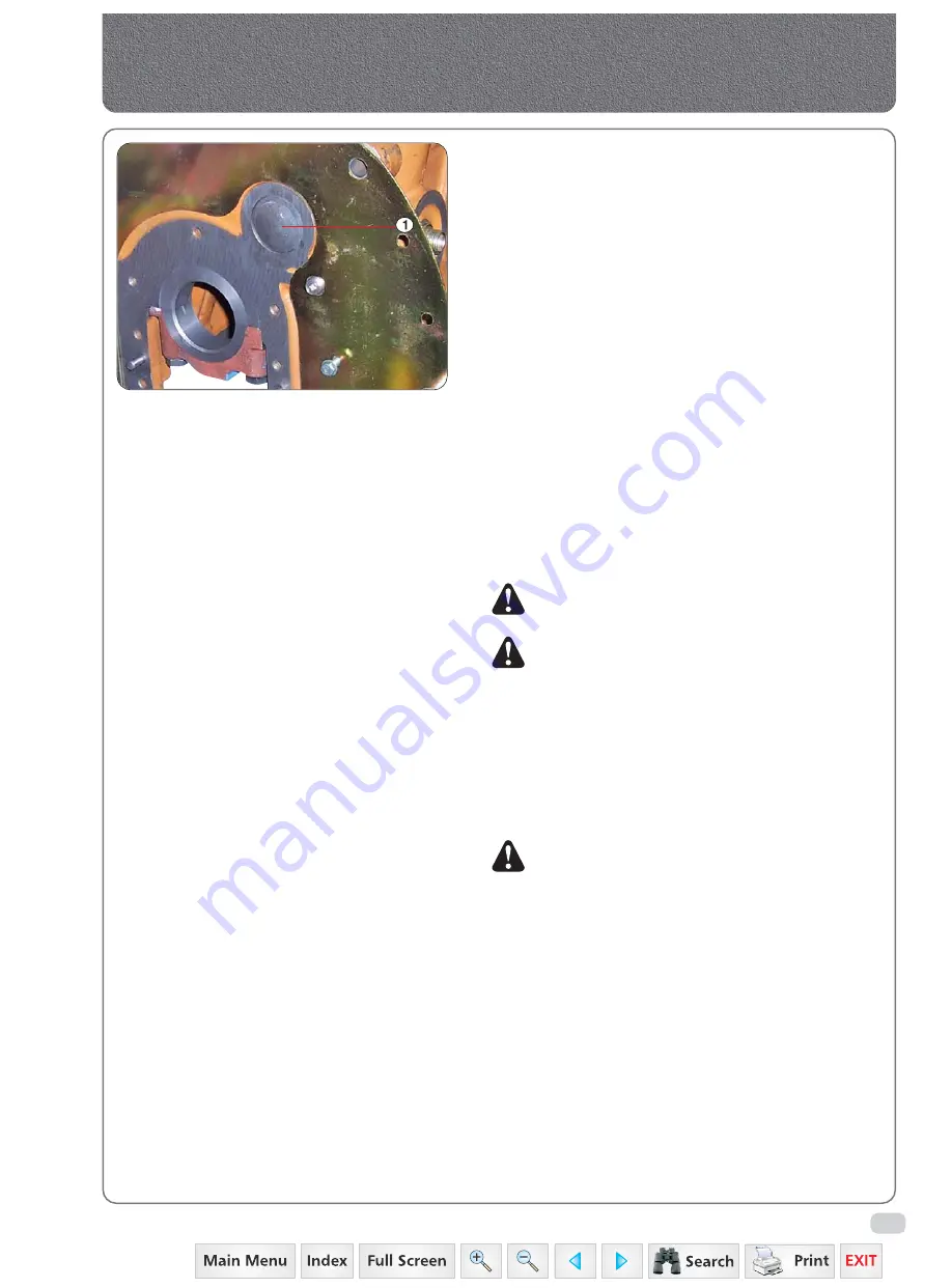
Use a long bar from the front of the crankcase
and drive out the expansion plug (1-6).
e)
Remove the camshaft bearings (2-4) from the
crankcase.
2.
INSTALLATION
a)
Press the centre bearing into position aligning the
hole in the bearing with the hole in the crankcase.
b)
Press the front and rear bearings into position
ensuring that the edge marked “FRONT” is to the
front of the crankcase and that the holes in the
bearings line up with those in the crankcase.
c)
Line bore the bearings to the dimensions in
specifications.
d)
After reaming, blow out the crankcase and oil
ways to remove all foreign material.
Note:
Ensure that the rear bearings is pressed in flush
with the front of the bore in the crankcase.
Note:
Bearings supplied for service are supplied
semi-finished and must be line reamed to
specified dimension after assembly.
a) After reaming thoroughly blowout the
casting and oil ways to ensure that there
is no metal deposit left.
b) Examine the tappet for signs of wear.
c) Do not attempt to straighten or repair the
camshaft. If any parts are suspect they must
be replaced.
Note:
When the engine is in the upright position the
tappet must be inserted one at a time as the
camshaft is installed into the engine because
the tappets are held in position by the
camshaft. Possible the engine should be
supported in an inverted position.
a) Place tappet in position.
e)
Install the rear bearing expansion plug
(1-6) expansion plug using a good quality sealer
on the plug and seat.
f)
Install the flywheel.
g)
Install the camshaft in the crankcase taking care
not to damage the bearings. Engage the camshaft
gear with the crankshaft pinion to ensure that
single timing marks are in line with each other.
Secure the thrust plate to the crankcase with bolts
and lock washers and tighten to the same specified
torque.
Fig. 6
Timing Gear Train, Front Cover & Camshaft
Summary of Contents for 3535
Page 1: ...Click here to go on INDEX SERVICE MANUAL 3535 4035 4535 5035 GEAR 35 Series 4WD Main Page ...
Page 5: ......
Page 6: ...35 Series 4WD Model 3535 4035 4535 and 5035 SM June 08 Group A G e n e r a l General A1 A21 ...
Page 7: ......
Page 26: ......
Page 58: ......
Page 59: ...35 Series 4WD Model 3535 4035 4535 and 5035 SM June 08 CHAPTER 1 INTRODUCTION ...
Page 60: ......
Page 74: ......
Page 76: ......
Page 86: ......
Page 88: ......
Page 96: ......
Page 97: ...35 Series 4WD Model 3535 4035 4535 and 5035 SM June 08 CHAPTER 4 LUBRICATION SYSTEMS ...
Page 98: ......
Page 102: ......
Page 104: ......
Page 110: ......
Page 112: ......
Page 124: ......
Page 126: ......
Page 133: ...35 Series 4WD Model 3535 4035 4535 and 5035 SM June 08 CHAPTER 8 COOLING SYSTEM ...
Page 134: ......
Page 143: ...35 Series 4WD Model 3535 4035 4535 and 5035 SM June 08 CHAPTER 9 AIR CLEANER ...
Page 144: ......
Page 149: ...35 Series 4WD Model 3535 4035 4535 and 5035 SM June 08 CHAPTER 10 FUEL SYSTEM ...
Page 150: ......
Page 168: ...35 Series 4WD Model 3535 4035 4535 and 5035 SM June 08 Group D C l u t c h Clutch D1 D10 ...
Page 169: ......
Page 179: ......
Page 180: ...35 Series 4WD Model 3535 4035 4535 and 5035 SM June 08 CHAPTER 1 TRANSMISSION ...
Page 181: ......
Page 200: ...35 Series 4WD Model 3535 4035 4535 and 5035 SM June 08 CHAPTER 2 REAR AXLE ...
Page 201: ......
Page 208: ...35 Series 4WD Model 3535 4035 4535 and 5035 SM June 08 CHAPTER 3 DIFFERENTIAL ...
Page 209: ......
Page 222: ...35 Series 4WD Model 3535 4035 4535 and 5035 SM June 08 CHAPTER 4 DIFFERENTIAL LOCK SYSTEM ...
Page 223: ......
Page 227: ......
Page 228: ...35 Series 4WD Model 3535 4035 4535 and 5035 SM June 08 CHAPTER 5 REAR PTO COVER ...
Page 229: ......
Page 231: ......
Page 232: ...35 Series 4WD Model 3535 4035 4535 and 5035 SM June 08 CHAPTER 6 WET CLUTCH PTO ...
Page 233: ......
Page 236: ...35 Series 4WD Model 3535 4035 4535 and 5035 SM June 08 CHAPTER 7 BRAKES ...
Page 237: ......
Page 243: ......
Page 245: ......
Page 270: ......
Page 296: ...Wiring Diagram 35 Series G 28 35 Series 4WD Model 3535 4035 4535 and 5035 SM June 08 ...
Page 298: ......
Page 303: ...H 7 35 Series 4WD Model 3535 4035 4535 and 5035 SM June 08 STEERING SYSTEM CIRCUIT Steering ...
Page 316: ......
Page 318: ......
Page 358: ......
Page 359: ......
Page 367: ...Range Section Transmission ...


