TWIN F 3.0 A / TWIN F 3.0 U
D1 5002BA1-GB01
29
•
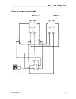
Press DOWN button (6) until the lift stops automatically (Figure 3);
N
OTE
:
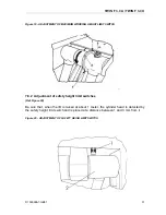
IF LOWERING IS NOT CARRIED OUT BY THE LIFT OR THE LIFT IS BLOCKED BEFORE THE
DETECTION BY THE SAFETY HEIGHT LIMIT SWITCH
,
OIL IN EXCESS FROM SECONDARY CYLINDERS
MUST BE REMOVED
.
If the lift does not low, push at the sametime with the down button (6) the oil discharge
button (13) and immediately release it.
W
ARNING
!
C
ARRY OUT THIS OPERATION ONLY AND EXCLUSIVELY WHEN THE LIFT
IS WITHOUT CHARGE
.
•
Press the SAFETY down button (7) (Ref. Figure 3).
•
If the runways are not levelled, restart bleeding operations (as described
previously).
7.6 Checks and inspections
7.6.1 Mechanical
checks
•
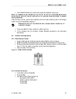
grease sliding seats of blocks placed under platforms and on bases;
•
platform levelling and alignment (as per measurement showed on Figure 18);
•
lift fixing to the ground with 8 anchor bolts (Ref. Figure 18) (min. recommended
size
ø = 16 mm
), bolts, connectors and connections tightened.
•
clean all parts of the machine
Figure 18 - FIXING ON THE GROUND
7.6.2 Electrical
checks
•
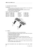
connections as per diagrams
•
lift
grounding
•
operation of the following devices:
top position limit switch
bottom position limit switch
P1 levelling
P2 levelling
Summary of Contents for Twin Series
Page 4: ...TWIN F 3 0 A TWIN F 3 0 U D1 5002BA1 GB01 II ...
Page 6: ...TWIN F 3 0 A TWIN F 3 0 U D1 5002BA1 GB01 IV ...
Page 8: ...TWIN F 3 0 A TWIN F 3 0 U D1 5002BA1 GB01 VI ...
Page 10: ...TWIN F 3 0 A TWIN F 3 0 U D1 5002BA1 GB01 VIII ...
Page 14: ...TWIN F 3 0 A TWIN F 3 0 U D1 5002BA1 GB01 4 ...
Page 19: ...TWIN F 3 0 A TWIN F 3 0 U D1 5002BA1 GB01 9 Figure 2 LIFT ...
Page 21: ...TWIN F 3 0 A TWIN F 3 0 U D1 5002BA1 GB01 11 Figure 3 CONTROL DESK ...
Page 34: ...TWIN F 3 0 A TWIN F 3 0 U D1 5002BA1 GB01 24 ...
Page 45: ...TWIN F 3 0 A TWIN F 3 0 U D1 5002BA1 GB01 35 ...
Page 46: ...TWIN F 3 0 A TWIN F 3 0 U D1 5002BA1 GB01 36 ...
Page 51: ......

