TWIN F 3.0 A / TWIN F 3.0 U
D1 5002BA1-GB01
28
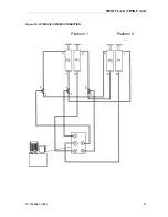
7.4 Electrical system connection
(Ref. Figure 17)
•
Connect magnetic proximity pickups of both the platforms to the control desk
following the numbering indicated on the cables.
•
Connect the external power supply to the positions indicated in Figure 7
•
Ensure that the lift is suitably grounded
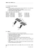
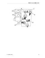
Figure 17 - ELECTRICAL SYSTEM CONNECTION
1=brown wire FC safety height
4=brown wire
FC safety height
2=blak wire
FC safety height
5=blak wire
FC safety height
3=blue wire
FC safety height
6=blue wire
FC safety height
7=brown wire FC auto-levelling
10=brown wire
FC auto-levelling
8=black wire FC auto-levelling
11=blak wire
FCS auto-levelling
9=blue wire
FC auto-levelling
12=blue wire
FC auto-levelling
7.5 Starting
•
Be sure the working area is free from people and objects.
•
Be sure the electrical system feeding voltage is equal to that of the control box
supplied with the lift (
230 V
or
400 V
);
•
Verify that the control desk is powered.
•
Pour oil in the tank (about
15 litres
).
•
Supply power to the lift by means of a local protected energy source;.
•
Verify that the motor direction of rotation is that shown on the label; if not
interchange the phases.
•
Press the UP button (5) (Ref. Figure 3) until the lift reaches the maximum
height
•
Effect discharge of the cylinder pushing the UP button (5) and at the same
time the override button (13) (ref. Fig. 3)
N.B. WAIT FEW MINUTES UNTIL AIR, MIXED WITH OIL IN THE TANK, COMES
OUT.
Summary of Contents for Twin Series
Page 4: ...TWIN F 3 0 A TWIN F 3 0 U D1 5002BA1 GB01 II ...
Page 6: ...TWIN F 3 0 A TWIN F 3 0 U D1 5002BA1 GB01 IV ...
Page 8: ...TWIN F 3 0 A TWIN F 3 0 U D1 5002BA1 GB01 VI ...
Page 10: ...TWIN F 3 0 A TWIN F 3 0 U D1 5002BA1 GB01 VIII ...
Page 14: ...TWIN F 3 0 A TWIN F 3 0 U D1 5002BA1 GB01 4 ...
Page 19: ...TWIN F 3 0 A TWIN F 3 0 U D1 5002BA1 GB01 9 Figure 2 LIFT ...
Page 21: ...TWIN F 3 0 A TWIN F 3 0 U D1 5002BA1 GB01 11 Figure 3 CONTROL DESK ...
Page 34: ...TWIN F 3 0 A TWIN F 3 0 U D1 5002BA1 GB01 24 ...
Page 45: ...TWIN F 3 0 A TWIN F 3 0 U D1 5002BA1 GB01 35 ...
Page 46: ...TWIN F 3 0 A TWIN F 3 0 U D1 5002BA1 GB01 36 ...
Page 51: ......


